EasyManua.ls Logo

Braeburn 1220NC User Manual

Braeburn 1220NC
10 pages
To Next Page IconTo Next Page
Page #1 background imageLoading...
Page #1 background image
This thermostat requires 24 Volt AC Power or two (2) properly installed
“AA Alkaline batteries for proper operation. When connecting 24 Volt
AC Power the batteries may be installed as a backup.
For use only as described in this manual. Any other use
will void warranty.
1020NC
Single Stage Heat / Cool
Conventional and Heat Pump
1
Specifications
2
About Your Thermostat
3
Installation
4
System Testing
5
Setting User Options
6
Operating Your Thermostat
7
Additional Operation Features
8
Thermostat Maintenance
®
Warning
Turn off power to the heating or cooling
equipment before installation.
Attention
For installation by experienced service
technicians only.
1220NC
Up to 2 Heat / 1 Cool
Conventional and Heat Pump
Read all instructions before proceeding.
This thermostat is compatible with:
• Singlestageheat/coolconventionalandheatpumpsystems
• Conventionalsystemsupto2heat/1cool(1220NConly)
• Singlecompressorheatpumpsystemswithanauxiliaryheatstage(1220NConly)
• 250–750millivoltheatonlysystems
Electrical and control specifications:
•ElectricalRating:24VoltAC
•1ampmaximumloadperterminal
•ACPower:18–30VoltsAC
•DCPower:3.0VoltDC(2“AAAlkalineBatteriesIncluded)
•ControlRange:45°–90°F(7°–32°C)
•TemperatureAccuracy:+/-1°F(+/-.5°C)
Terminations
•1020NC–Rc,Rh,O,B,Y1,W1,G,C
•1220NC–Rc,Rh,O,B,Y1,E/W1,G,W2,C
1
Specifications
1020NCW-100-03
Non-Programmable
Thermostats
Model number is located on back of thermostat
Detailed
Installer Guide
Question and Answer IconNeed help?

Do you have a question about the Braeburn 1220NC and is the answer not in the manual?

Braeburn 1220NC Specifications

General IconGeneral
TypeNon-Programmable Thermostat
Program ScheduleNo
Stages1 Heat / 1 Cool
ChangeoverManual
TerminalsR, W, Y, G
BacklightNo
Hold FunctionYes
Filter Change AlertNo
Power Source24VAC (Battery optional for memory backup)
DisplayDigital LCD
CompatibilitySingle Stage Heating and Cooling Systems
Temperature Range40°F to 90°F (4°C to 32°C)

Summary

Specifications

Installation

Thermostat Location

Guidance on optimal placement for thermostat installation based on air circulation and average room temperature.

Install the Sub-Base

Instructions for removing and mounting the thermostat sub-base to the wall.

Provide Power

Details on connecting 24VAC power or installing backup batteries for thermostat operation.

Connect Your Wires

Wiring terminations and typical configurations for conventional and heat pump systems.

Set Installer Switches

Attach Thermostat to Sub-Base

System Testing

Operating Your Thermostat

Setting the System Control Mode

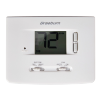
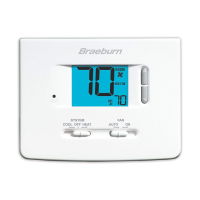
Explanation of system modes (COOL, OFF, HEAT, EMER) and how to select them.

Temperature Adjustment

How to use the up/down arrows to change the desired temperature setting.

Additional Operation Features

Compressor Protection

Explanation of the automatic delay feature to prevent compressor damage from short cycling.

Related product manuals