Factory Setting
Switch Default Options Comments
5
Heat Pump Systems (cont.)
NOTES - Heat Pump Systems
[1]Ifbatteriesareinstalledthe24VoltACcommonconnectionisoptional.
[2]SelectOforcoolactiveor Bforheatactive.
[3]InstallaeldsuppliedjumperbetweentheW2 and Eterminalsif
thereisnoseparateemergencyheatrelayinstalled.
Provide disconnect and overload protection as required.
CONV/HP CONV
F/C F
HE/HG HG
Set Installer Switches
4
CONV Selectforconventionalsystems
HP Selectforheatpumpsystems
F Selectforfahrenheittemperaturescale
C Selectforcelsiustemperaturescale
HG Selectforgasheat
HE Selectforelectricheat
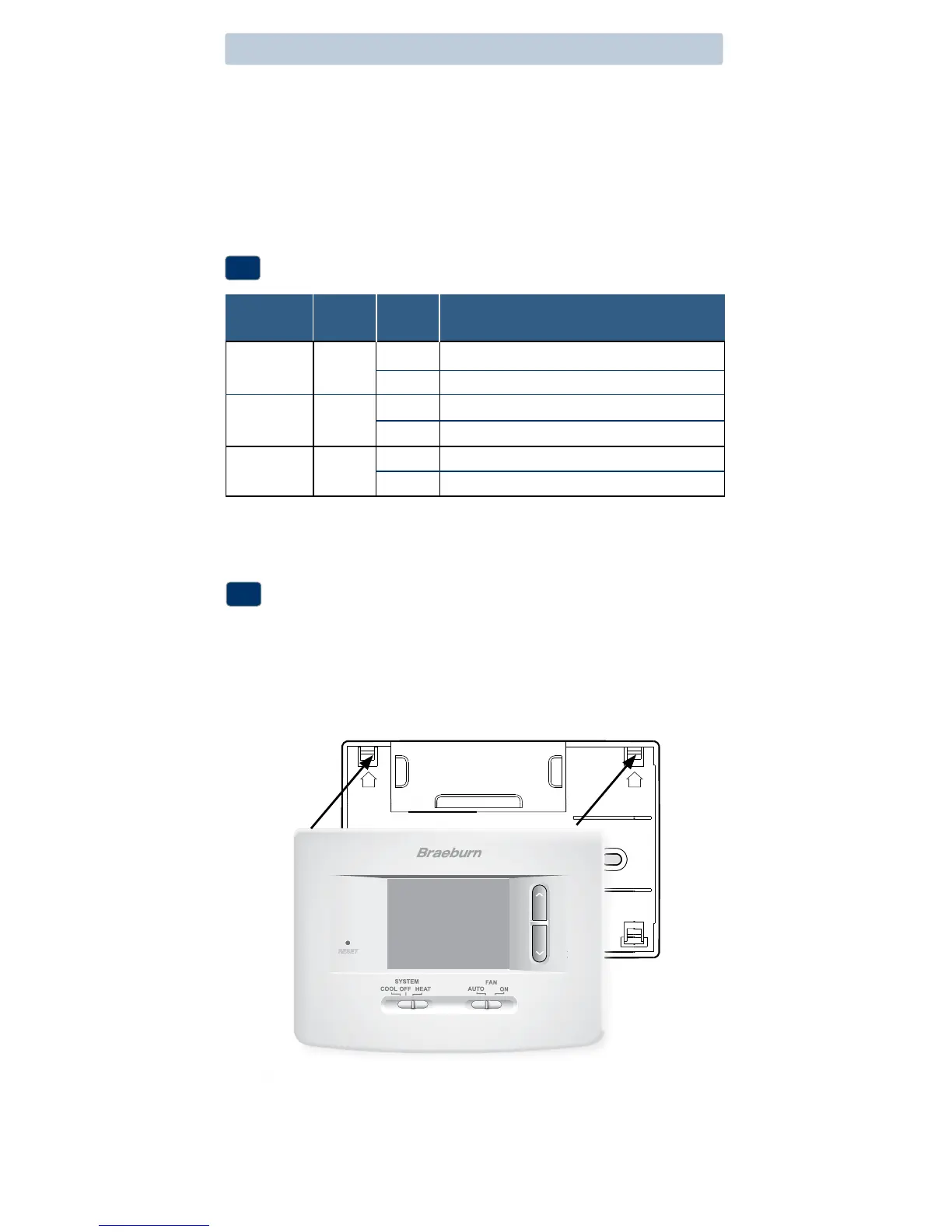
Attach Thermostat to Sub-Base
5
1.Lineupthethermostatbodywiththesub-base.
2.Carefullypushthethermostatbodyagainstthesub-baseuntilitsnaps
intoplace.
3.Insertquickreferencecardintoslotontopofthermostat.
NOTE: Installer switches are located on the back of the thermostat. The
reset button must be pressed after making any changes to these switches.
UP UP
 Loading...