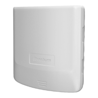
3.4 Conventional System Wiring
Note: For a heat pump system, see Section 3.5.
Connect a conventional heating system to
the zone panel as shown.
For a single stage heating and cooling
system, the 2nd stage connections are
not used.
For a system using a dual transformer,
open jumper J1 (see Configuration
section, Figure 4). Make sure the neutrals
(common) are connected.
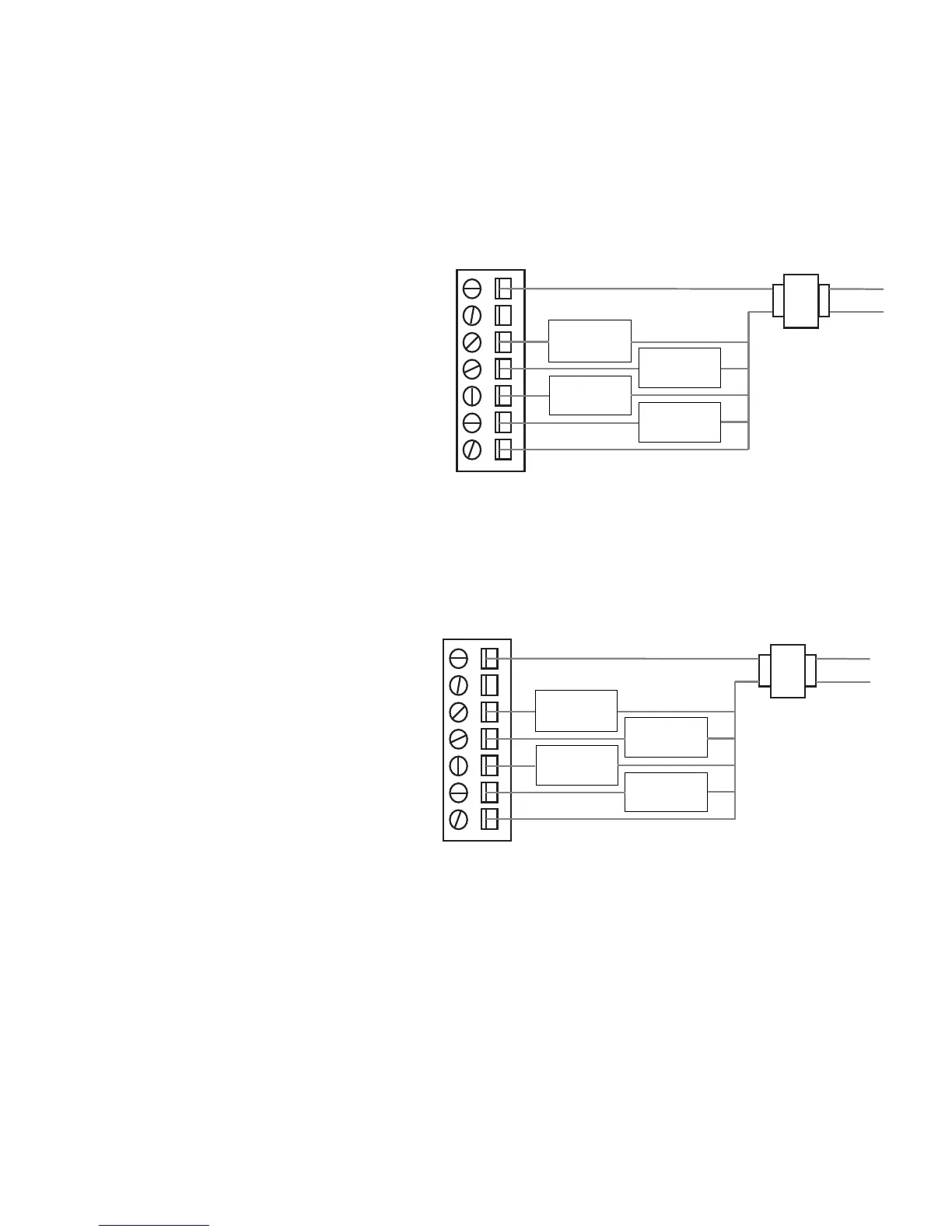
3.5 Heat Pump System Wiring
Connect a single or multi-stage
heat pump system to the zone panel
as shown.
A conventional thermostat may be used
with a heat pump system, however,
emergency heat will be controlled by
the panel emergency heat switch or the
optional remote emergency heat switch.
For a single-stage system, the auxiliary
heat control is not used. For a multi-
stage system, the compressor controls
are not used.
• Use DIP switch 1 to select between conventional and heat pump system.
• Use DIP switch 3 for heat pump reversing valve control. Setting 0 means that the O/B terminal is
active in a cooling call. Setting B means that the O/B terminal is active in a heating call.
RH
RC
Y
G
W1
EH
W2
O/B
C
C
HOT
1st stage
compressor
control
1st stage
fan
control
1st stage
heat
control
2nd stage
heat
control
24 VAC
RH
RC
Y
G
W1
EH
W2
O/B
C
C
HOT
1st stage
compressor
control
1st stage
fan
control
aux heat /
E-heat
control
reversing
valve
24 VAC
5