FEATURES
SPECIFICATIONS
1
2
2
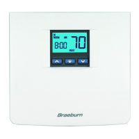
• Contemporary styling with large display
• 7 Day Programming Flexibility
• AC Powered with Battery Back-up (2 AA Alkaline ba tteries included)
• Relay Outputs for Maximum Compatibility
• Easy Access Front Battery Door
• Pre-programmed for quick installation
• Meets Title 24 and Energy Star
(Energy Saving Guidelines)
• Vacation "HOLD" Mode
• Compressor Short Cycle Protection
• Adjustable 1st & 2nd Stage Temperature Differentials
• Residual Cooling Fan Delay
• Efficient Recovery Mode (ERM™)
• Low battery Indication
• LED Status Indicator
• Quick Wiring Terminal Block
• High Temperature Safety Switch
INSTALLATION
3
3.1
Replacing Existing Thermostat
1.
Always turn off power to the air conditioning or heating system prior to removing existing
thermostat.
2.
Remove the cover of your old thermostat and locate the wire terminals. Do not remove
wires from terminals yet.
3.
Using small pieces of masking tape label wires prior to removal from terminals. Use the
chart below to determine the new terminal designations for your new thermostat.
4.
After labeling and removng all wires from terminals, unscrew the existing thermostat
mounting base from wall. Make sure to secure wires to prevent them from slipping back
into the hole in the wall.
NOTE:
This thermostate is for use on low voltage 24 Volt AC multi-stage heat pump systems with up to two stages of heating
and two stages of cooling and requires a transformer common wire for proper installation. This thermostat is nt for use on single
stage heating or cooling systems
• Electrical Rating: 24 Volt AC (18-30 Volt AC)
2 amp maximum load per terminal
4 amp total maximum load (all terminals)
• Control Range: 45˚ - 90˚ F (7˚ - 32˚ C)
• Accuracy: +/- 1˚ F (+/- .5˚ C)
• AC Power: 18-30 Volt AC
• DC Back-Up Power: 3.0 Volt DC (2 AA Alkaline batteries included)
• Compatibility: Multi-stage heat / cool systems
with up to two stages of heating and two stages
of cooling.
• Terminations: R, Y1, Y2, W1, W2, G, O, B, C
Old Terminal from New Terminal for
Existing Thermostat New Thermostat Terminal Description
R, V-VR or VR-R R 24 VAC
Y, Y1 or M Y1 1st Stage Cooling
Y2 Y2 2nd Stage Cooling
W1 W1 1st Stage Heating
W2 or W-U W2 2nd Stage Heating
G or F G Fan Control
O or R O Reversing Valve (Cooling)
B B Reversing Valve (Heating)
C, X or B C Transformer Common
3
INSTALLATION
3
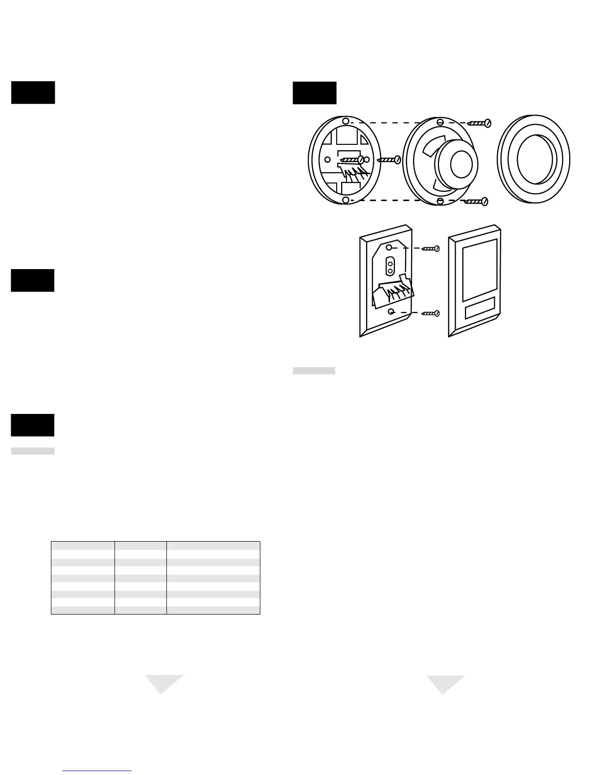
Illustration of round and rectangular
mechanical thermostat exploded
views.
3.2
Installing Your New Thermostat
NOTE: If you are installing this thermostat in a new installation be sure to locate
the thermostat 4 to 5 feet above the floor in accordance with applicable building
codes. Make sure to install the thermostat in a location that provides good airflow
characteristics and avoid areas behind doors, near corners, air vents, direct sunlight
or near any heat generating device. Installation in any of these areas could impact
thermostat performance.
1.
Always turn off power to the air conditioning or heating system prior to installing your
new thermostat.
2.
Place system switch on front of thermostat to OFF position.
3.
Place fan control switch on front of thermostat to AUTO position.
4.
Remove front of thermostat body from rear body by pressing release latch on bottom of
front body.
5.
Place the thermostat rear body (mounting plate) against wall in the desired thermostat
location.
6.
Guide thermostat wires through center hole in rear body. Continue to hold rear body
against wall.
7
. Mark placement of mounting holes as appropriate and drill using a 3/16" drill bit.
8.
Gently tap supplied plastic anchors into the holes in the wall.
9.
Place the thermostat rear body (mounting plate) against the wall in the desired location
making sure the mounting holes are aligned as appropriate and the thermostat wires
are properly inserting through opening in middle of rear body.
10.
Fasten the rear body (mounting plate) to wall using supplied screws.
11.
Connect wires to quick wiring terminal block as appropriate using the new terminal
designations. Refer to Wiring Diagram section of this manual if required for assistance.
12.
Make sure all of the wire connections are secure and are not touching any other
terminal to prevent electrical shorts and potential damage to the thermostat.
cont.
 Loading...