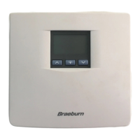
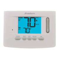
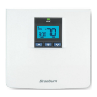
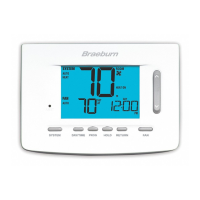
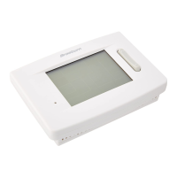
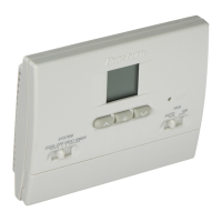
MODEL
5000
USER MANUAL
Premier Series
5-2 Day Programmable
Single Stage Heat/Cool
Digital Thermostat
Compatible with low voltage single stage gas,
oil or electric heating or cooling systems,
including single stage heat pumps. This
thermostat can also be used on 250mv to
750mv millivolt heating only systems. Do not
use this thermostat on applications with
voltages above 30 Volts AC.
READ ALL INSTRUCTIONS BEFORE PROCEEDING
© 2005 Braeburn Systems LLC • Patents Pending • All Rights Reserved. Pub. No. 5000-100-005
WARNING!
Important Safety Information
• Always turn off power to the air conditioning or heating system prior to installing,
removing, cleaning or servicing thermostat.
• Read this manual thoroughly prior to installing, programming or operating
this thermostat.
• This thermostat is designed for use with a 24 Volt-AC low voltage single stage
gas, oil or electric heating or cooling systems, including single stage heat
pumps. This thermostat can also be used on 250mv to 750mv millivolt heating
only systems.
• Do not use this thermostat on applications with voltages above 30 Volts AC.
• This thermostat requires two (2) properly installed "AA" alkaline batteries to
provide power for the thermostat to properly control the system operation.
• Wiring must conform to all building codes and ordinances as required by local
and national code authorities having jurisdiction.
• Do not short (or jumper) across terminals on the gas valve or at the heating or
cooling system control board to test the thermostat installation. This could
damage the thermostat and void the warranty.
• Do not select COOL mode of operation if the outside temperature is below
50˚ F (10˚ C). This could damage the controlled cooling system and cause
personal injury.
• This thermostat should only be used as described in this manual. Any other use
is not recommended and will void the warranty.
SPECIFICATIONS
1
1
• Electrical Rating: 24 Volt AC (18-30 Volt AC)
1 amp maximum load per terminal
2 amp total maximum load (all terminals)
• Control Range: 45˚ - 90˚ F (7˚ - 32˚ C)
• Accuracy: +/- 1˚ F (+/- .5˚ C)
• DC Power: 3.0 Volt DC (2 AA Alkaline batteries included)
• Compatibility: Compatible with low voltage single stage gas, oil or electric
heating or cooling systems, including single stage heat pumps. This thermostat
can also be used on 250mv to 750mv millivolt heating only systems.
• Terminations: Rc, Rh, G, W, Y, B, O
INSTALLATION
2
2.1
Replacing Existing Thermostat
1.
Always turn off power to the air conditioning or heating system prior to removing
existing thermostat.
2.
Remove the cover of your old thermostat and locate the wire terminals. Do not remove
wires from terminals yet.
3.
Using small pieces of masking tape, label wires prior to removal from terminals. Use
the chart below to determine the new terminal designations for your new thermostat.
Old Terminal from New Terminal for
Existing Thermostat New Thermostat Terminal Description
V or Rc Rc Cooling Transformer
M, 4, Rh, or R Rh Heating Transformer
G or F G Fan Control
H, W or 4 W Heating Control
Y Y Cooling Control
B B Reversing Valve (Heating)
O O Reversing Valve (Cooling)
C None-Cap the wire 24 Volt AC, Transformer Common
CONTENTS
SPECIFICATIONS
INSTALLATION
TESTING YOUR NEW THERMOSTAT
PROGRAMMING
ADDITIONAL OPERATION FEATURES
TROUBLESHOOTING
WIRING DIAGRAMS
1
2
3
4
5
6
7