Electrical Connections
6-3
Digital Compact
2002 BRANSON Ultrasonics Digital Compact Version 22.08.2002
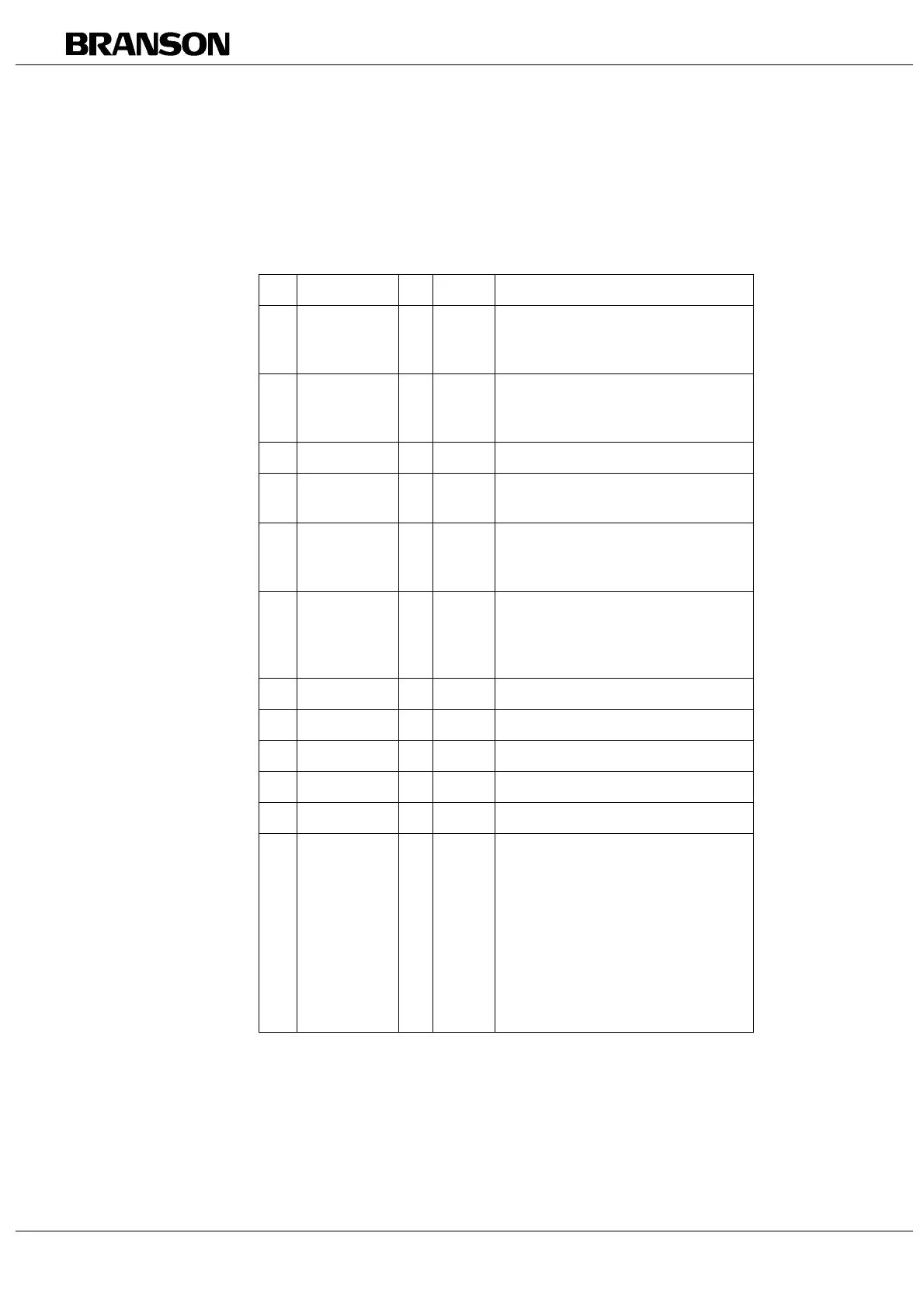
6.2 Control/ Alarm Connector (J3)
Tab. 6-3 Pin assignment of the J3 connector (15 pins)
Pin Assignment I/O Type Description
1 Window high > digital active low: when exceeding the
maximum power during the weld,
the Window high signal is output.
2 O/L inverted
(Ready)
> digital active 24 V
inactive Low (0 V)
inverted signal from Pin 4
3 GND Ext. analog 0 V
4 O/L (Ready) > digital active: low inactive: 24V
Output signal „Overload“ to PLC
5 Start < digital 24V PLC input signal
As long as the signal is present, the
ultrasonic output is active.
6 Seek + < digital 24V PLC input signal
At 24V (with reference to pin 14) a
frequency seek is started
min signal duration: 20ms
7 Ref. 10 V > analog 10V reference voltage, 5mA max.
8 GND analog 0 V
9 Weld on > digital active: low
10 free
11 + 24 V Ext. < digital external 24V power supply
12 Window low > digital active: low
If during energy welding, the start
signal is lost before completion of
the weld cycle, or if the maximum
weld time of 5 s is exceeded, then
the weld is terminated, and a Win-
dow low error message is output. If
the minimum power is not reached
during a weld, the Window low
signal is output.