EasyManua.ls Logo

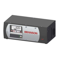
Branson DCX A Series User Manual

Branson DCX A Series
188 pages
To Next Page IconTo Next Page
Page #1 background imageLoading...
Page #1 background image
DCX A
Power Supply
Original Instructions
100-412-197 - REV. 07
Instruction Manual
Branson Ultrasonics Corporation
41 Eagle Road
Danbury, CT 06813-1961 USA
(203) 796-0400
http://www.bransonultrasonics.com

Table of Contents

Questions and Answers:

Branson DCX A Series Specifications

General IconGeneral
BrandBranson
ModelDCX A Series
CategoryPower Supply
LanguageEnglish

Summary

Chapter 1: Safety and Support

1.1 Safety Requirements and Warnings

Explains safety symbols, warnings, and requirements for safe operation and handling.

1.2 General Precautions

Covers essential safety precautions for servicing and operating the equipment.

1.3 Warranty Statement, Disclaimer

Details the product warranty policy, coverage, and limitations.

1.4 How to Contact Branson

Provides essential contact information for technical support, parts, and repair services.

1.5 Returning Equipment for Repair

Outlines the procedure for returning equipment for repair, including obtaining an RGA number.

1.6 Obtaining Replacement Parts

Guides users on how to order necessary replacement parts and lists contact details.

Chapter 2: Introduction

2.1 Models Covered

Lists all DCX A Power Supply models detailed in this manual.

2.2 Compatibility with other Branson Products

Details compatibility of the power supply with various Branson converters.

2.3 Features

Describes the key features and advanced capabilities of the DCX A Power Supply system.

2.4 Controls and Indicators

Explains the function and purpose of the DCX A Power Supply's front panel controls and indicators.

2.5 Welding Systems

Explains the principle of ultrasonic welding and lists system applications.

2.6 Glossary of Terms

Defines key terminology used throughout the ultrasonic welding manual.

Chapter 3: Delivery and Handling

3.1 Shipping and Handling

Covers environmental specifications and precautions for safe shipping and handling of the power supply.

3.2 Receiving

Provides a step-by-step procedure for inspecting the power supply upon delivery.

3.3 Unpacking the Power Supply

Details the necessary steps for safely unpacking the power supply unit.

3.4 Take Inventory of Small Parts

Lists included small parts, power supply assemblies, and system cables.

3.5 Returning Equipment

Refers to contacting customer service for approval before returning equipment.

Chapter 4: Technical Specifications

4.1 Technical Specifications

Lists critical environmental and electrical specifications for the DCX A Power Supply.

4.2 Physical Description

Describes the physical dimensions and weight of the DCX A Power Supply in different configurations.

4.3 Declaration of Conformity

Presents the official declaration of the product's compliance with relevant directives and standards.

Chapter 5: Installation and Setup

5.1 About Installation

Introduces installation guidance and includes important safety warnings for handling heavy objects.

5.2 Installation Requirements

Details location, environmental, electrical, and pneumatic requirements for successful installation.

5.3 Installation Steps

Provides comprehensive step-by-step instructions for installing the power supply and its connections.

5.4 Power Supply Setup

Explains selectable power supply configurations and key setup features.

5.5 Assembling the Acoustic Stack

Guides users on the correct procedure for assembling the converter, booster, and horn.

5.6 Converter Cooling

Details necessary procedures for cooling the converter to ensure optimal performance and reliability.

5.7 Testing the Installation

Directs users to the ultrasonics test procedure to verify the installation.

5.8 Still Need Help?

Offers further assistance and directs users to contact local Branson representatives.

Chapter 6: Converters and Boosters

6.1 Converters and Boosters

Illustrates various converters and boosters compatible with the DCX A Power Supply.

Chapter 7: Operation

7.1 Setting Primary Parameters

Guides on selecting Weld Modes (Continuous, Time, Energy, Peak Power, Ground Detect).

7.2 Setting the Amplitude

Explains how to set the ultrasonic amplitude using front panel controls or external interfaces.

7.3 Resetting the Power Supply Alarms

Describes procedures for resetting power supply alarms based on specific settings.

7.4 Configuring the Power Supply Registers

Provides steps for configuring power supply registers and understanding their functions.

7.5 LCD Bar-Graph

Explains how to interpret the LCD bar-graph for power and frequency readings during operation.

7.6 Ultrasonics Test Procedure

Details the procedure for testing the ultrasonic power output of the stack without a load.

7.7 Using the I/O Connections

Guides users on utilizing the power supply's I/O connections for automation and external control.

Chapter 8: Maintenance

8.1 General Maintenance Considerations

Covers general warnings and notices related to safe and proper servicing of the power supply.

8.2 DCX A Power Supply Preventive Maintenance

Outlines essential preventive maintenance tasks, including cleaning and reconditioning components.

8.3 Recommended Spare Stock

Lists recommended system cables and suggested spare parts for the power supply.

8.4 Circuit Diagram

Provides the interconnect diagram for troubleshooting and understanding the system's electrical layout.

8.5 Troubleshooting

Offers systematic steps for troubleshooting common electrical, power, and weld cycle problems.

8.6 Cold Start Procedure

Explains how to perform a cold start to restore factory default settings and resolve system issues.

Appendix A: Alarms

A.1 Overload Alarms (Group 0)

Lists and describes overload alarms that can occur during a weld cycle, potentially aborting it.

A.2 Cutoff Alarms (Group 1)

Lists and describes cutoff alarms that limit parameters, stopping ultrasonics but allowing cycle continuation.

A.3 Setup Alarms (Group 2)

Lists and describes alarms that are specific to the setup phase of the system.

A.4 Cycle Modified Alarms (Group 3)

Lists and describes alarms that modify cycle parameters due to changing conditions, aborting the cycle.

A.5 Warning Alarms (Group 4)

Lists and describes warning alarms for unexpected conditions that do not abort the cycle.

A.6 Limit Alarms (Group 5)

Lists and describes limit alarms reported at the end of a weld cycle without aborting it.

A.7 Equipment Failure Alarms (Group 6)

Lists and describes alarms indicating user equipment malfunction before cycle starts.

A.8 No Cycle Alarms (Group 7)

Lists and describes time-out errors or missing inputs that abort a cycle.

A.9 Communication Failure Alarms (Group 8)

Lists and describes alarms related to communication issues between system processors.

A.10 Hardware Alarms (Group A)

Lists and describes alarms indicating internal equipment failures, preventing cycle starts.

A.11 Non-Cycle Overload Alarms (Group B)

Lists and describes overloads that occur outside of a weld cycle, not affecting cycle count.

Appendix B: Timing Diagrams

B.1 Timing Diagrams

Presents various timing diagrams illustrating signal sequences and operational flows for different modes.

Appendix C: Signal Diagrams

C.1 Signal Diagrams

Illustrates signal diagrams for key operational modes like Continuous and Time.

Related product manuals