64 100-412-197 REV. 07
5.3.12 Default Branson User I/O Connector PIN Assignments
Software V6.0 - V6.4
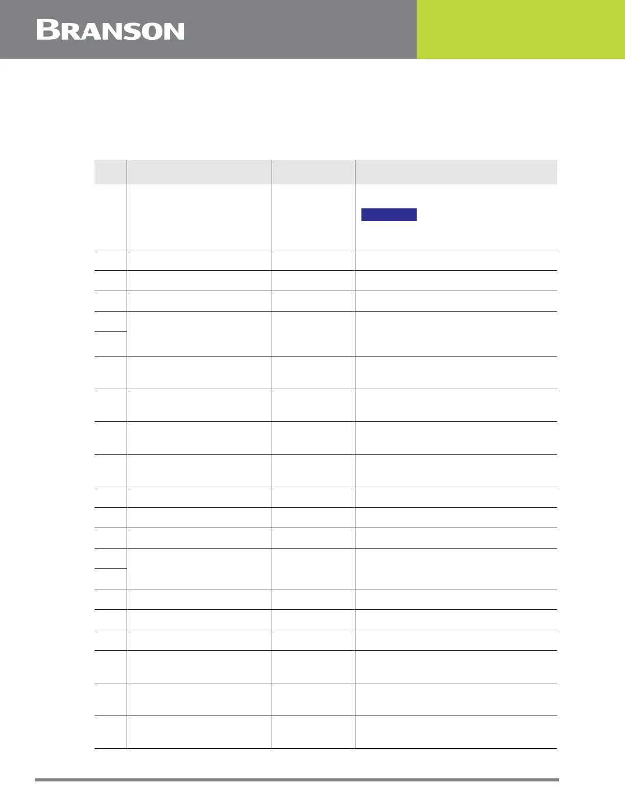
Table 5.15 Default Branson User I/O Connector PIN Assignments, V6.0
Pin Function I/O Type Values
1 STD-External Start Input Digital
Apply +24 VDC to run cycle
NOTICE
DCX A Power Supply must be in
ready mode before External Start.
2 STD-External Seek Input Digital Apply +24 VDC to perform a seek
3 STD-External Reset Input Digital Apply +24 VDC to reset alarm
4 STD-Memory Clear Input Digital Apply +24 VDC to clear memory
5
+24 VDC Source
I/O Signal
Source
+24 V, 250 mA max. (sourced from
the customer supplied 24 V external
power supply).
6
7 STD-Ready
Output
Digital
+24 V indicates the system is ready
8 STD-Sonics Active
Output
Digital
+24 V indicates ultrasonics are
active
9 STD-General Alarm
Output
Digital
+24 V indicates an alarm occurred
10 STD-Seek/Scan Out
Output
Digital
+24 V indicates either Seek or a
Scan is in progress
11 STD-Recall Preset 1 Input Digital Bit 0 for preset recall binary code
12 STD-Recall Preset 2 Input Digital Bit 1 for preset recall binary code
13 STD-Recall Preset 4 Input Digital Bit 2 for preset recall binary code
14
+24 VDC Return and
I/O Return
I/O Signal
Return
Return for all pins except pins 17,
18, 24, and 25
15
16 STD-Recall Preset 8 Input Digital Bit 3 for preset recall binary code
17 Amplitude In Input Analog 1 V to + 10V (10% to 100%)*
18 Frequency Offset Input Analog 1 V to + 9V (5 V is zero offset)
19 STD-Amp1 Amp2
Output
Digital
Indicates amplitude setting 0 V for
Amplitude 1, +24 V for Amplitude 2
20 STD-Overload Alarm
Output
Digital
+24 V indicates an overload alarm
occurred.
21 STD-Start Signal Release
Output
Digital
+24 V indicates start signal can be
removed.

 Loading...
