Page 12
Figure H
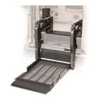
Figure G
Lift Installation Instructions
1
Lift Positioning (continued)
1/2"
Minimum
Clearance
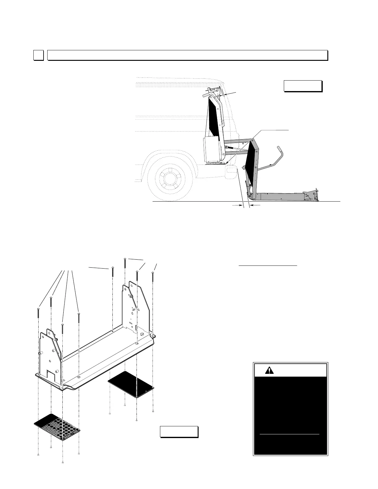
Base Plate
Wedges
1" Minimum Clearance
Rear Door and
Extensive
Floor-to-Ground
Installations
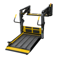
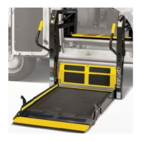
Rear Door and Extensive
Floor-to-Ground Installations:
Position the lift in the rear door
opening as outlined on pages
10 and 11. Depending on the
particular lift model installed
and the particular vehicle
configuration, the top of the lift
may need to be tilted inboard
slightly to provide the minimum
1/2" clearance between the lift
and the door(s) and/or to
increase platform and vertical
arm kick-out (to provide ad-
equate clearance between lift
and vehicle). See Figure G.
There must be a minimum 1"
clearance between the lift
(vertical arms and/or automatic
inboard roll stop) and the
vehicle during lift operation.
Base Plate Mounting BoltsBase Plate
Mounting Bolts
Base Plate Wedges:
Four base plate wedges are
supplied for shimming (tilting lift).
The plastic wedges provide full
depth base plate support. Use
one or two wedges per base
plate end as needed. Position
the wedges by aligning the
mounting holes in the wedges
with the base plate mounting
holes as shown in Figure H.
Check for obstruc-
tions such as gas
lines, wires, exhaust,
etc. before drilling or
cutting. Failure to do
so may result in
serious bodily injury
and/or property
damage.
 Loading...