Page 63
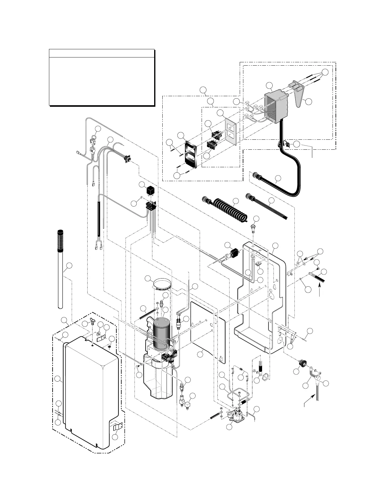
Rear Pump Module Diagram
Apply red #271 Thread Locker Loctite
®
to the three pump mounting bolts (items
28 and 29) if a blue nylon patch is not
present on the bolts when retrofitting an
M268 pump assembly. Loctite
®
is
available from The Braun Corporation
under part number 11522-1.
Pump Mounting Bolts
Power Cable
from Battery
External
Chassis
Ground
Cable
Not applicable for
Control Box 6D
and Harness 7D.
59
4
38
32
36
31
30
3
34
1
33
41
21
24
40
39
29
28
37
37
44
19
26
28
27
43
To
Remote
Interlock
To N.C. on Unfold/Down Microswitch
To N.O. on Up/Fold Microswitch
To COM. on Unfold/Down Microswitch
To COM. on Up/Fold Microswitch
To N.C. on Up/Fold Microswitch
To N.O. on Unfold/Down Microswitch
To N.C. on Bridge Microswitch
To COM. on Bridge Microswitch
17
6
12
8
9
10
11
7C
7B
42
7A
DOWN
U
P
UN
FOLD
(O
UT)
FO
L
D
(IN
)
13
14
15
16
16
18
35
2
+-
38
22
23
25
20
2
5
51
50
47
50
50
45
52
49
48
46
53
 Loading...