11
Series 5A and Series 5B I.S. Valve Status Monitor
Installation, Operation and Maintenance Manual
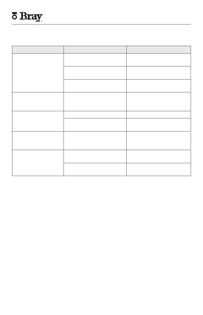
14. Troubleshooting Chart
Problem Possible Cause Solutions
Signal is not received
Wiring is not connected inside
VSM
Rewire field wiring and check
applied torque to terminal block
Cams are set outside of actuator
range
Adjust cam position
Damage to switches Check power ratings of switches
versus application
Open signal is received
in close position (or vice
versa)
Field wiring is reversed Rewire field wiring
Corrosion inside unit
Condensation forming Seal conduit opening
Water leaking in Check all seals and possible water
entry through conduit
Visual indication is
opposite of actuator
position
Visual indication was reversed or
VSM was mounted 90°
Reverse visual indication or re-
mount VSM.
VSM does not rotate
Bracket or adapter does not mate
properly with actuator.
Check bracket and adapter for
proper fit and adjust as needed.
Actuator is not moving as com-
manded
Check troubleshooting chart in
actuator IOM. Check field wiring.