3
Series 5A and Series 5B I.S. Valve Status Monitor
Installation, Operation and Maintenance Manual
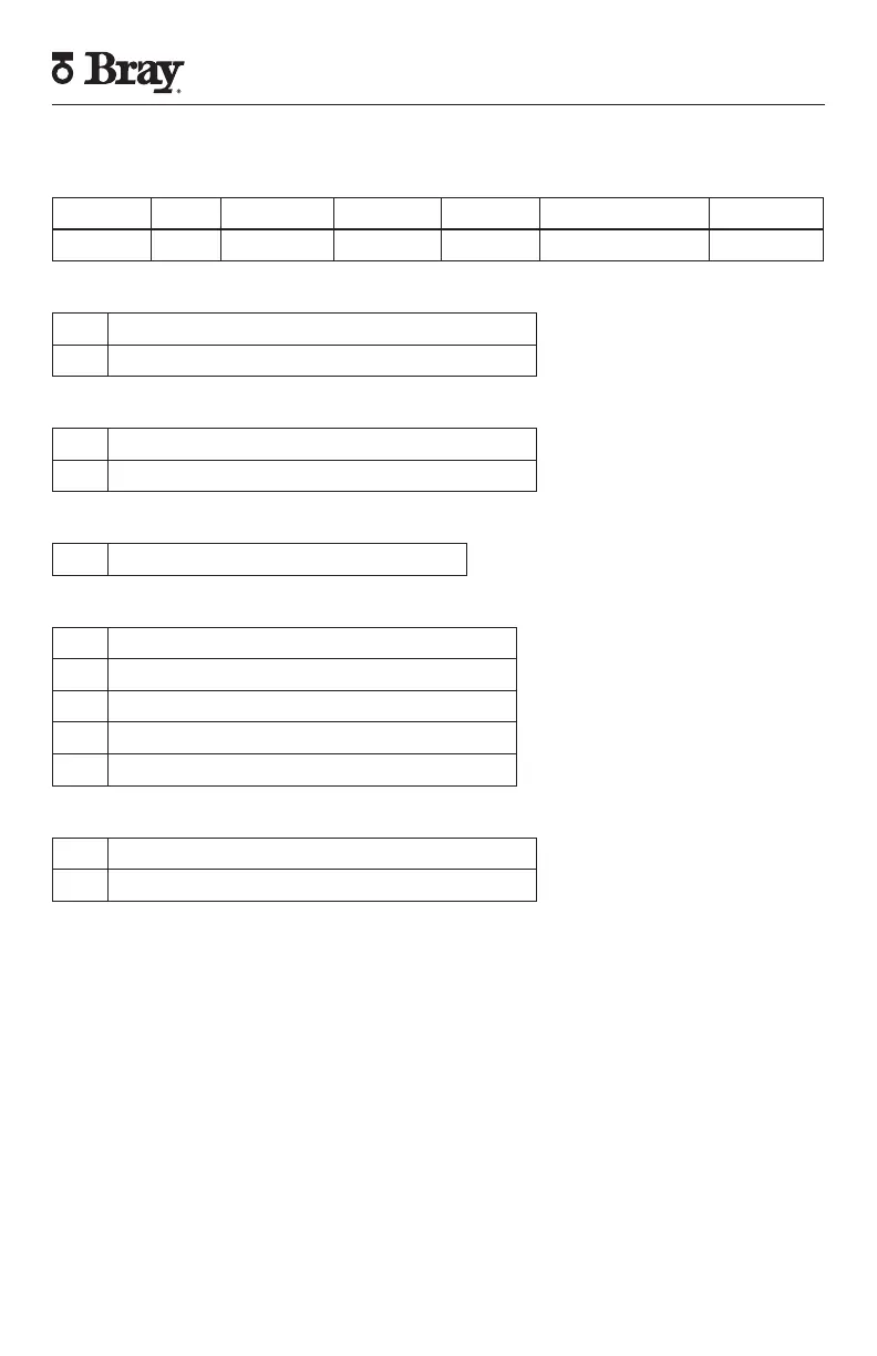
4. Part Numbering System Reference Chart
Series Housing Product Switch Configuration Trim
5X 000 H -126 S C T
5X – Designates Housing Size
5A Type 4,4x, IP 66/67, Max 2 switches
5B Type 4,4x, IP 66/67, Max 6 switches
H – Designates Housing Style
0 Imperial
5 Metric
S – Designates Switch Option
H Intrinsically Safe, 2-wire, Proximity Switch
C – Designates Switch Configuration
2 2 Switches
3 3 Switches, Independent
4 4 Switches, Independent
5 4 Switches (2 Independent, 2 Auxiliary)
6 6 Switches (4 Independent, 2 Auxiliary)
T – Trim
536 Polyester coated aluminum
517 Resin
5. Introduction
The Bray Series 5A and 5B Intrinsically Safe
Valve Status Monitors (VSMs) provide visual and
electrical indication of position of any VDI/VDE
3845 compliant quarter-turn device. The S5A and
S5B I.S. VSMs are designed to operate in multiple
hazardous locations.
6. Principle of Operation
Bray Series 5A and 5B I.S. VSMs are comprised of a
NEMA Type 4/4X, IP66/67 housing (resin housings
are IP66/67/68 (1 meter, 1 hour) with external
position indicator and two conduit entries, cam
shaft with self-locking cams, elevated terminal block,
internal grounding screw, and mounting bracket.
The VSM is coupled to the quarter turn device via the
cam shaft. Rotation of the cam shaft, in turn, drives
switch activation. The angular position in which
the switches activate can be adjusted through the
self-locking cams. Proximity activation of switches
provides electrical feedback of achieved position
through field wiring to a control network.