BRAY Series 70 Electric Actuator
Operation and Maintenance Manual
8
field Or faCTOry insTallable OPTiOns
tOrque SWitcheS
Torque switches are a factory installed and calibrated option
available for all Series 70 units. Installation is simple, but
due to the requirement for special calibration equipment, it
is not recommended for eld installation. In fact, modifying
the factory torque setting voids the actuator warranty.
The unique mechanism is extremely accurate and has
excellent repeatability. The worm is pinned to the worm
shaft, which is held in position with a stack of disc springs
at both ends. The torque transmitted through the worm to
the output worm gear acts directly against the disc springs,
which compress proportionately. The worm and worm shaft
shift longitudinally as a result.
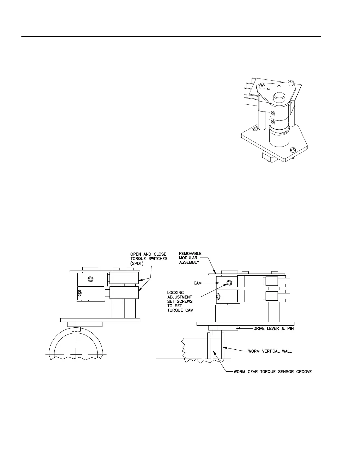
A specially designed drive lever and pin is incorporated
into the worm, providing the prole for the torque switching
mechanism. A drive lever & pin rides in the worm gear torque
sensor groove, and in turn drives a cam. The cam then actu-
ates its electrical switch, which interrupts the power to the
motor winding when
the torque exceeds
the setting. The motor
can still be powered to
run in the opposite di-
rection, the switch will
release automatically.
tOrque SWitch MechaniSM
Switching Mechanism

 Loading...


