BRAY Series 70 Electric Actuator
Operation and Maintenance Manual
17
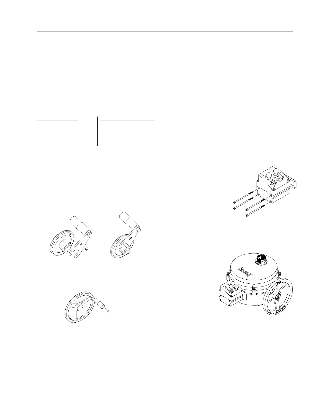
SPinner
A spinner is available to ease and speed the manual override
of the Bray Series 70 actuator. The Housing Size 6 units
mount the spinner on a lever which screws onto the back of
the handwheel. The Housing Size 12-180 units mount the
spinner on the rim of the handwheel. Note that care should
be exercised in the use of spinner equipped handwheels.
Rapid operation of the handwheel to close the valve may
cause water hammer. Also, rapid travel into a travel stop
may cause damage.
SPinner Kit cOnSiStS Of:
For Housing Size 6 For Housing Sizes 12-180
Spinner and lever assembly Socket head shoulder bolt,
Flat head socket cap screw, 1/4-20UNC x .75
#10-32UNF x 3/8 Spinner handle
tOOlS required:
• For socket head shoulder bolt and at head capscrew
• Hex key,
1
/
8
” for Housing Size 6
• Hex key,
3
/
16
” for Housing Sizes 12-180
inStallatiOn PrOcedure:
• For Housing Size 6 units simply position the lever onto
the back of the handwheel then screw the at head cap
screw in to place from behind.
• For Housing Size 12-180 units, put the socket head
shoulder bolt through the spinner handle and screw it
rmly into the handwheel rim.
lOcal cOntrOl StatiOn (Single PhaSe POW-
ered actuatOrS)
Bray’s local control station gives the user the ability to locally
override the actuator electrically. The station is open / stop /
close operation in the local control mode. Red and green end
of travel indication lights are also provided. Depending on
how it is wired the control station
can be used on the on - off
units and the servo controlled modulating units. Optional
key operated locking switches are available.
Note: The control station used with On - Off S70 and that
used with modulating S70 have different contact blocks
internally, the correct part number must be used to ensure
you order the correct unit (see price sheet).
lOcal cOntrOl StatiOn Kit cOnSiStS Of:
1. Local control station assembly
2. Four socket head cap screws, #10-24UNC x 4.50 long,
for mounting the station to the actuator
3. A gasket for sealing the station to the actuator
4. Wiring diagram
tOOlS required:
• For tapping control station mounting holes on actuator,
#10-24UNC Tap.
• For wiring Screwdriver,
3
/
16
” at blade.
• For mounting and cover screws Hex key,
5
/
32
”
inStallatiOn PrOcedure:
1. Tap #10-24UNC holes
using the cored holes on
the side of actuator.
2. Adhere the gasket to the
control box.
3. Mount the control box
to the actuator using
the 4 long socket head
capscrews.
4. Wire the control box to the actuator in accordance to
the wiring diagram provided. The local control station
contains no terminal strips, and all wiring is direct to the
switches and lights via 2” x
3
/
4
” NPT holes in bottom of
housing.
Ordering the control station with optional pin con-
nector receptacles
will eliminate the
necessity of eld
wiring. The units
will be completely
factory wired and
tested.
Note: The inclined
cover of the local
control station can be
mounted in any of its
four symmetrical posi-
tions. If eld wiring is required , rst mount the base to the
actuator, then remove the cover to gain access for wiring.
*Local Control Station requires a dedicated set of auxiliary
switches for control station use only. Two additional adjust-
able auxilary switches are needed for remote indication of
open/close position in ONOFF congurations

 Loading...


