

R
Richard JenkinsJul 27, 2025
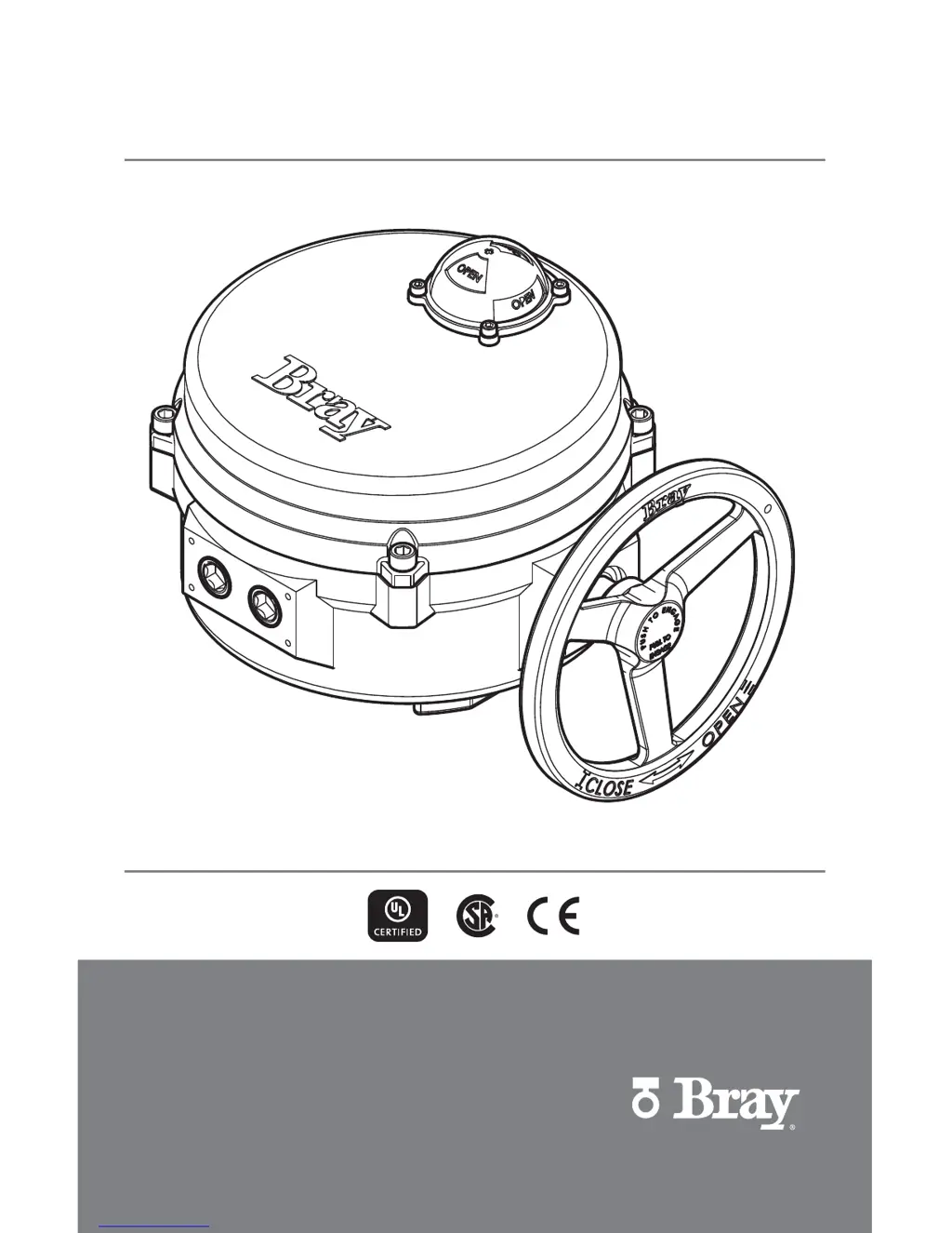
What to do if my Bray Controller actuator does not operate?
- MmichaelmillerJul 27, 2025
If your Bray Controller actuator isn't working, here are a few things to check: * Ensure the override isn't engaged by pushing the handwheel in all the way. * Verify the wiring and power supply are correct. * If the actuator motor has overheated, allow it time to cool down.


