7
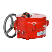
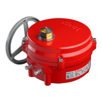
Series 70 Electric Actuator
Installation, Operation and Maintenance Manual
Wiring the Actuator
Turn off all power and lockout/tag out service panel
before installing or modifying any electrical wiring.
1. Take the actuator cover off. The cover should be
kept on hand for reference.
2. Wire the actuator as per the wiring diagram attached
to the inside of the actuator cover.
NOTICE
Power and control wiring should use separate conduit
entries.
NOTICE
A minimum of 18 AWG wire is recommended for all
field wiring.
Terminals directly mounted on the actuator switch
plate accept wire sizes ranging from 14 to 22 AWG.
Terminals of internally mounted electronics modules
accept wire sizes ranging from 14 to 24 AWG.
NOTICE
The conduit connections must be properly sealed to
maintain the weatherproof integrity of the actuator
enclosure.
Setting Travel Limit Switches
NOTICE
If the unit came assembled to a valve, the switches
have been factory-set and DO NOT need adjustment.
Bray uses its patented cam design along with two SPDT
mechanical switches to set the ‘Open’ and ‘Closed’
position of the valve. The green cam actuates the ‘open’
switch when the actuator reaches the ‘open’ position.
Similarly, the red cam actuates the ‘closed’ switch when
the actuator reaches the ‘closed’ position.
Standard factory setting of the travel limit switches allows
90° travel between open and close positions. Cams for
each switch are adjustable for applications where less
than 90-degree travel is desired between the open and
closed positions.
Cam
Locking
Screw
Figure 6. Two SPDT Travel Limit Switches
Follow the steps below to adjust the travel limit cams.
NOTE: For Actuator Size 130, 180, ignore steps 1 and 10.
1. Remove the indicator rotor by pulling away from the
indicator shaft as shown in Figure 7.
Figure 7. Indicator rotor pulled up from the indicator shaft.
2. Manually operate the actuator clockwise until the
valve reaches the desired ‘closed’ position.
3. Loosen the cam locking screw shown in Figure 6.
 Loading...