10
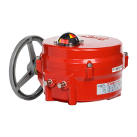
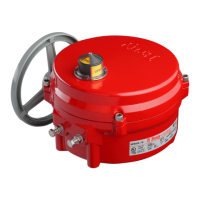
Series 70 Electric Actuator
Installation, Operation and Maintenance Manual
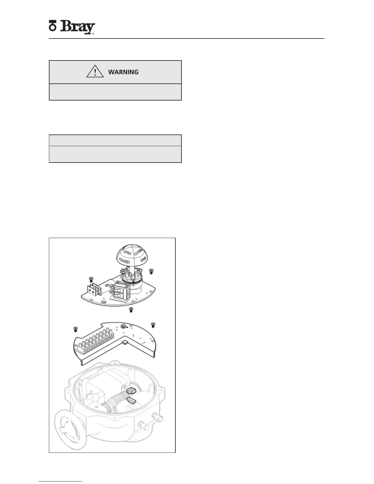
Disassembly and Assembly
Turn off all power and lockout/tag out service panel
before installing or modifying any electrical wiring.
1. Disconnect external wiring from terminals.
2. Disconnect motor wires from the main terminal
strip (motor neutral, open, and close)
NOTICE
Removal of switch plate with torque switches will
void warranty.
3. To remove the switch plate:
a. Follow after disconnecting external wires and
motor wires.
b. Unscrew the seven Phillips head mounting
screws.
c. Lift the switch plate(s) out as an assembly with
the indicator shaft attached.
d. NOTE: Do not misplace shaft coupler, insert,
or mounting screws.
Figure 10. S70, Actuator Size 003, 006 – switch plate removed.
4. To replace the switch plate:
a. Engage handwheel.
b. Place insert into the worm segment.
c. Place and center shaft coupler onto insert.
d. Align indicator shaft with groove in coupler
and gently place switch plate into position.
e. Check alignment of override switch activation
pin.
f. Slowly turn handwheel to ensure that the
indicator shaft is fully engaged in coupler.
g. Secure the switch plate with seven Phillips
head mounting screws in a “star” pattern.
h. Disengage the handwheel.
5. To remove the indicator shaft from the switch plate:
a. Follow after removing the switch plate.
b. Remove the retaining ring from the shaft,
located underneath switch plate.
c. Press the shaft out, from the bottom of the
switch plate.
d. NOTE: Provide support to top of switch plate
so that components on top of the switch plate
are not damaged during this procedure.
6. To remove the bearing from the switch plate:
a. Follow after the removing the indicator shaft.
b. Press the bearing from the top of the switch
plate to remove the bearing.
c. To replace, press bearing (700000-72701534)
into switch plate from the bottom of switch
plate.
7. To replace the indicator shaft in the switch plate:
a. Gently press the indicator shaft from the top of
the switch plate until the cams are flush with
the top surface of the switch plate. NOTE:
Provide support for the press fit bearing during
this step.
b. Replace retaining ring (070375-74503534) on
the shaft, located underneath switch plate.
c. Gently press the indicator shaft from the
bottom until the retaining ring is flush with
bottom of the bearing.
d. Test indicator shaft for tight fitment and ease
of rotation.
8. Other switch plate components:
a. Most components can be removed from the
switch plate without removal of the switch
plate.
 Loading...