15
Series 70 Electric Actuator
Installation, Operation and Maintenance Manual
Installation Procedure:
Turn off all power and lockout/tag out service panel
before installing or modifying any electrical wiring.
The local control station is mounted to the S70 against
the conduit openings using 4 pre-drilled and tapped
mounting holes.
1. Remove the S70 actuator cover and set aside in a
safe location.
2. Remove all conduit plugs and external connections
on the S70 that may already be in place.
3. Remove 4 short bolts and washers that were pre-
installed on the exterior of the S70 base, surrounding
the conduit entries.
4. Adhere the gasket to the control station base.
5. Slide o-rings onto the long mounting bolts until
flush with bottom of bolt head.
6. Mount the control station to the actuator using the
4 mounting bolts.
7. Wire the control station to the actuator in accordance
to the wiring diagram provided.
NOTICE
Power and control wiring should use separate conduit
entries
NOTES:
• The local control station contains no terminal strips
and all wiring is direct to the switches and lights via
2 x ¾” NPT or holes in bottom of housing.
• Ordering the control station with optional pin
connector receptacles will eliminate the necessity
of field wiring. Not all possible options are available
with receptacles. Consult factory.
• Control station will be completely factory wired
and tested.
• Factory will need wiring diagram drawing number
of the existing unit if it is to be retrofit with a local
control station. New wiring diagram will be provided
based upon this information.
• Local control station can be ordered with key lockable
switches.
• Local control station requires a dedicated set of
auxiliary switches. These switches are required for
turning on or off the lights on the control station
to locally indicate actuator position.
• Alternative mounting kit can be ordered in case it is
preferred to mount the control station nearby but
not on the S70 actuator.
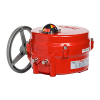
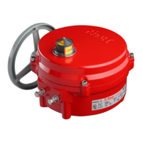
Battery Backup Unit
Bray offers a factory installable Battery Backup Unit
(BBU) for the 24 V Series 70 electric actuator.
In the event of power failure, the BBU will switch the
actuator to battery power to reach its fail position. After
the actuator has reached its fail position, the BBU goes
to ‘Standby Mode’ until external power is restored.
Once external power has been restored, the actuator
returns to the position corresponding to the control
signal present.
Figure 18. S70 with Battery Backup Unit.
Battery Backup Unit is available as a factory installable
option. For more information, please refer to the S70
24V Actuator with BBU Manual. This manual is available
on the company website (bray.com).
 Loading...