5
Series 70 Electric Actuator
Installation, Operation and Maintenance Manual
Servo NXT
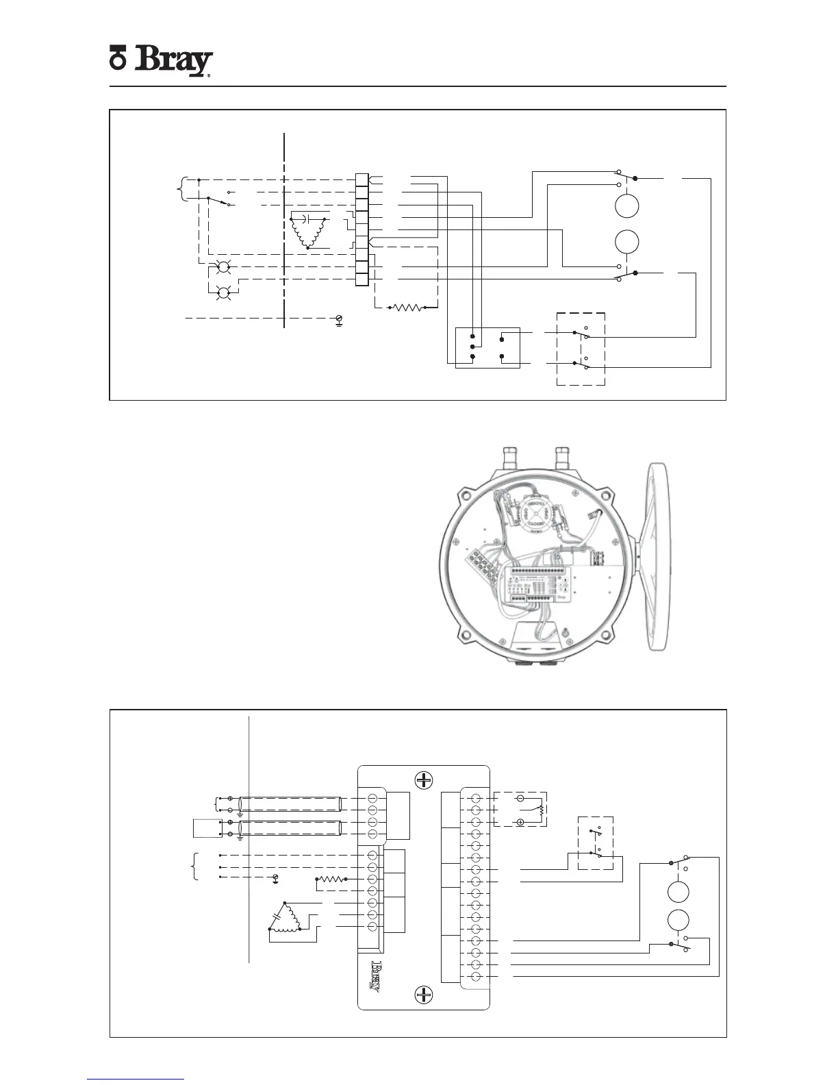
To control the actuator remotely from a process
controller in a modulating application, user must apply
the proper supply voltage and the configured control
signal to the Servo NXT electronics package. The control
signal may be applied locally from a hand-held signal
generator or remotely from a process controller.
For more information, please refer to the S70 Servo
NXT Manual. This manual is available on the company
website (bray.com).
Figure 4 - S70 with Servo NXT
SINGLE PHASE
POWER SUPPLY
GROUND
N
L
OPEN
BLUE
CLOSE
OPEN
CLOSE
(SEE NOTE 5)
FOR HEATER OPTION ONLY
RED
YELLOW OR
BLACK
O
C
N
MOTOR
YELLOW
YELLOW
RED
RED
RED
RED
BLUE
OVERRIDE SW
CLOSE
OPEN
RED
HEATER (OPTIONAL)
BLUE
BLUE
BLUE
BLUE
GREEN
CAM
RED
CAM
N.C.
COM
N.O.
N.C.
COM
N.O.
OPEN
CLOSE
COM
COM
N.C.
N.O.
N.C.
N.O.
CL
OP
N
MC
MO
INTERPOSING RELAY
1
2
3
4
5
6
7
8
9
Actuator shown in closed position
Figure 3 - Sample field wiring diagram for Series 70 actuator with I.R.B.
Actuator specific wiring diagram located inside actuator cover.
Figure 5 - Sample field wiring diagram for Series 70 actuator with Servo NXT.
Actuator specific wiring diagram located inside actuator cover.
FEEDBACK
POTENTIOMETER
WHITE
ORANGE
GREY
YELLOW
YELLOW
OVERRIDE SW
N.C.
N. O.
N.C.
N.C.
N. O.
N. O.
N.C.
N. O.
COM
COM
COM
COM
BLUE
BLUE
RED
RED
OPEN
CLOSE
GREEN
CAM
RED
CAM
COM
INPUT+
INPUT–
OUTPUT+
OUTPUT–
NEUTRAL
LIVE
NEUTRAL
CLOSE
LIVE
NEUTRAL
OPEN
WIPER
POWER
COM
CLOSE
COM
COM1
COM2
CLOSE
OPEN
COM1
COM2
CLOSE
OPEN
HW
OPEN
LIMIT SW
MOTOR
COMMAND
INPUT
POWER HEATER
HAND
WHEEL
CTRL BOX
FB POT
TORQUE SW
RED
YELLOW
OR BLACK
BLUE
HEATER
(OPTIONAL)
MOTOR
O
N
C

 Loading...