17
Series 70 Electric Actuator
Installation, Operation and Maintenance Manual
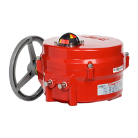
Figure 20. S70 with 5-pin receptacle and corresponding cord set.
Installation Procedure:
1. Screw the receptacle into the actuator conduit entry
using Teflon tape or similar.
2. Wire to the terminal strip according to the wiring
diagram or the field wiring requirements.
NOTES:
• Euro receptacles use 22 AWG wire rated at 250V,
4 Amp. Pin configuration interfaces with European
standards.
• Mini Receptacles use 18 AWG wire rated at 300V, 9
Amp. Pin configuration conforms to ANSI B93.55M.
• Factory will need wiring diagram drawing number
and model of the existing unit if it is to be retrofit with
receptacles. New wiring diagram will be provided
based upon this information.
• Some configurations may limit use of receptacles due
to number of wires entering through the conduit.
External Signal Feedback Potentiometer
Potentiometers are a field or factory installable option
for continuous duty actuators. Actuators which are
not continuous duty do not have a pot gear fitted
on their indicator shafts and must be fitted with a
new indicator shaft in the factory. S70 actuators fitted
with electronics for modulating applications already
fit a potentiometer and cannot fit a second. In this
case, retransmission of position is provided through
the modulating electronics package.
Feedback Potentiometer Kit:
• Potentiometer Assembly
• #6 Cross Drive Pan Head Screws (Qty:2)
• #6 Internal Lockwashers (Qty:2)
• 4-pole Terminal Strip
• Terminal Strip Marker
• Wiring Diagram
Tools Required:
• Screwdriver, 3/16” [5 mm] tip flat blade
• Screwdriver, No.2 Phillips
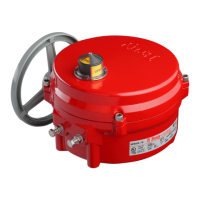
Figure 21. S70 Potentiometer installation.
1. Orient the actuator in the full open (counter
clockwise) position.
2. Install the potentiometer next to the indicator
shaft where two threaded holes are provided for
installation.
3. Align the raised green rib on pot gear with the
center line of the indicator shaft.
4. Push the assembly towards the cam to mesh the
gears, then tighten the mounting screws.
5. Rotate the actuator handwheel so that the red cam
lobe is facing the body of the potentiometer. Make
sure that the cam is not touching the potentiometer
assembly. Readjust the assembly position if necessary.
6. Cut the terminal marker to fit the 4-pole terminal
strip.
7. Mount the 4-pole terminal strip and marker on the
switch plate.
8. Wire the potentiometer to the terminal strip using
the new wiring diagram.
9. Adhere the new wiring diagram sticker to the inside
of the cover.
NOTE:
• Factory will need wiring diagram drawing number
and model of the existing unit if it is to be retrofit
with a potentiometer. New wiring diagram will be
provided based upon this information.
Raised
green rib
 Loading...