4
Series 70 Electric Actuator
Installation, Operation and Maintenance Manual
Actuation
Manual Operation
The manual override operates similar to a watch
adjusting knob. To engage the manual override, simply
pull the handwheel to its outermost position. A yellow
stripe is revealed to visually indicate manual override
engagement as shown in Figure 1. The two handwheel
positions, engaged and disengaged, are held in place
with the use of spring plungers. The handwheel remains
in position until physically moved.
Yellow Stripe
Figure 1 - Handwheel is engaged, revealing the yellow stripe.
Once the manual override is engaged, rotating the
handwheel in the clockwise direction will rotate the
output shaft in the clockwise (close) direction and
vice-versa.
To disengage the manual override, the handwheel needs
to be pushed towards the actuator until the ‘yellow
stripe’ is hidden.
A label on the handwheel hub warns users not to
exceed a specific ‘rim pull’ force, for each size of
actuator.
If the ‘rim pull’ force is exceeded, the roll pin securing
the handwheel onto the manual override shaft is
designed to shear, thus preventing serious internal
gearing damage.
Remote Operation
1. Verify that the main electric power supplied to the
actuator is in compliance with the specifications on
the actuator label.
2. Engaging the handwheel before or during the
application of a supply voltage will prevent the
actuator motor from operating.
3. If torque switches are installed in the actuator, an
over-torque condition will prevent the actuator
motor from operating in the direction of fault.
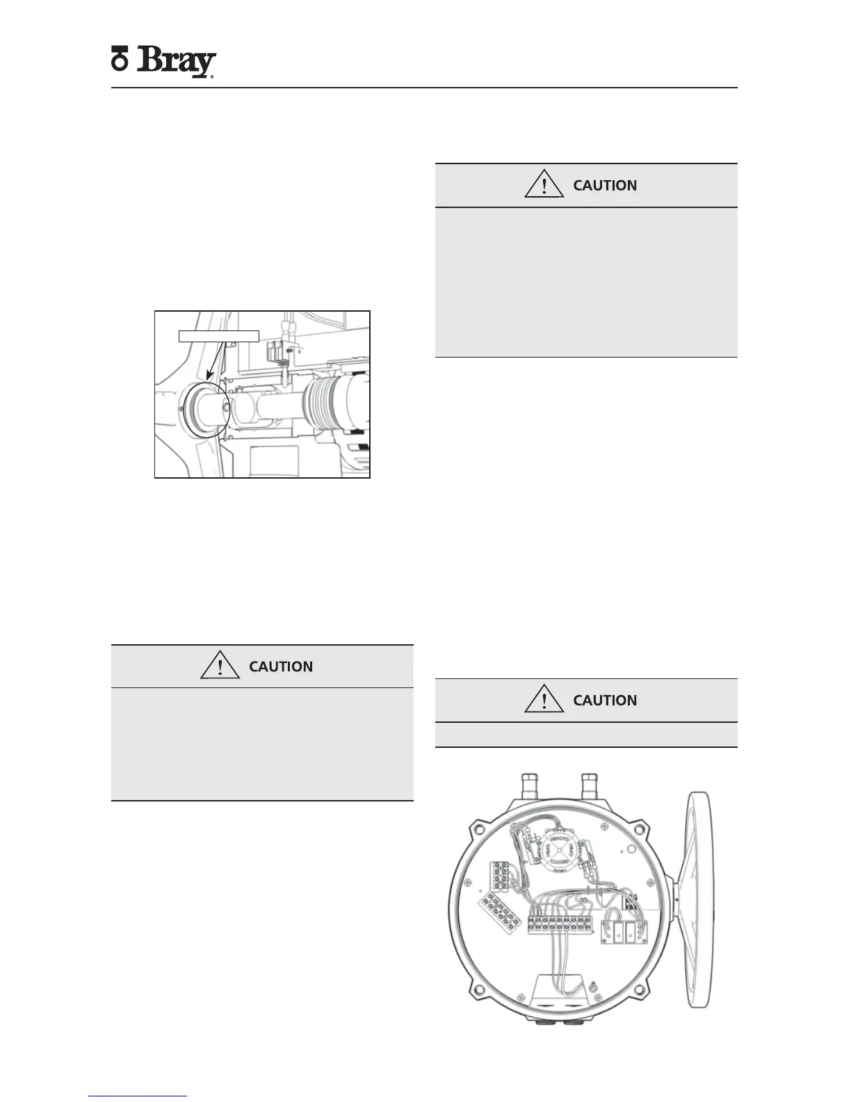
S70 On/Off Actuator with Interposing Relay
Board (I.R.B.)
The back feeding of one actuator by another one
wired in parallel is eliminated by using the I.R.B. If
actuator is running Open and customer switches
“instantaneously” to run Closed, the Open relay will
take time to ‘drop-out’ and the Close relay will take
time to ‘pull-in’ this time lapse is ~ 40ms. The time
delay provided by the I.R.B. will protect the switches
and gears from the controller’s instantaneous command
signal reversal. Current draws and field wirings are not
affected by adding I.R.B.
S70 120VAC I.R.B., auxiliary switch, heater, and torque
switch option are UL certified units
NOTE: The host controller should use a one second
time delay for command signal reversal.
Apply voltage to only one direction terminal at a time.
Figure 2 - S70 with I.R.B.
 Loading...