14
Series 70 Electric Actuator
Installation, Operation and Maintenance Manual
Heater Kit:
• Heater with flying leads
• Mounting Bracket
• #10 Pan Head Screw, Phillips Drive
Tools Required:
• Screwdriver, 3/16” [5 mm] tip flat blade
• Screwdriver, No.1 Phillips
Installation Procedure:
Turn off all power and lockout/tag out service panel
before installing or modifying any electrical wiring.
The heater is mounted through a hole provided in
the switch plate.
1. Place the heater snugly into its mounting bracket
until approx. 1/2 to 1” [13mm to 25 mm] is left
above the bracket.
2. Slip the heater into its mounting hole.
3. Align the fastening hole in the bracket with the
threaded screw hole in the plate and fasten the
heater to the switch plate.
4. Connect the heater wires to the terminal strip as
indicated on the wiring diagram.
Torque Switches
Mechanical Torque switches are a factory installed and
calibrated option available for all Series 70 actuators.
Installation is simple, but due to the requirement for
special calibration equipment, it is not available for
field installation. Modifying the factory torque setting
voids the actuator warranty. Removal of the switch
plate invalidates factory calibration
The worm is pinned to the worm shaft, which is held in
position with a stack of disc springs at both ends. The
torque transmitted through the worm to the output
worm gear acts directly against the disc springs, which
compress proportionately. The worm and worm shaft
shift axially as a result.
A specially designed drive lever and pin is incorporated
into a groove on the worm, providing the profile for the
torque switching mechanism. A drive lever & pin rides
in the worm gear torque sensor groove, and in turn
drives a cam. The cam then actuates its electrical switch,
which interrupts the power to the motor winding when
the torque exceeds the setting. The motor can still
be powered to run in the opposite direction. When
powered in the opposite direction, the tripped torque
switch will release automatically.
NOTICE
Torque switches are not field adjustable. Adjustment
of torque switches in the field will void warranty.
Removal of switch plate with torque switches in the
field will void warranty.
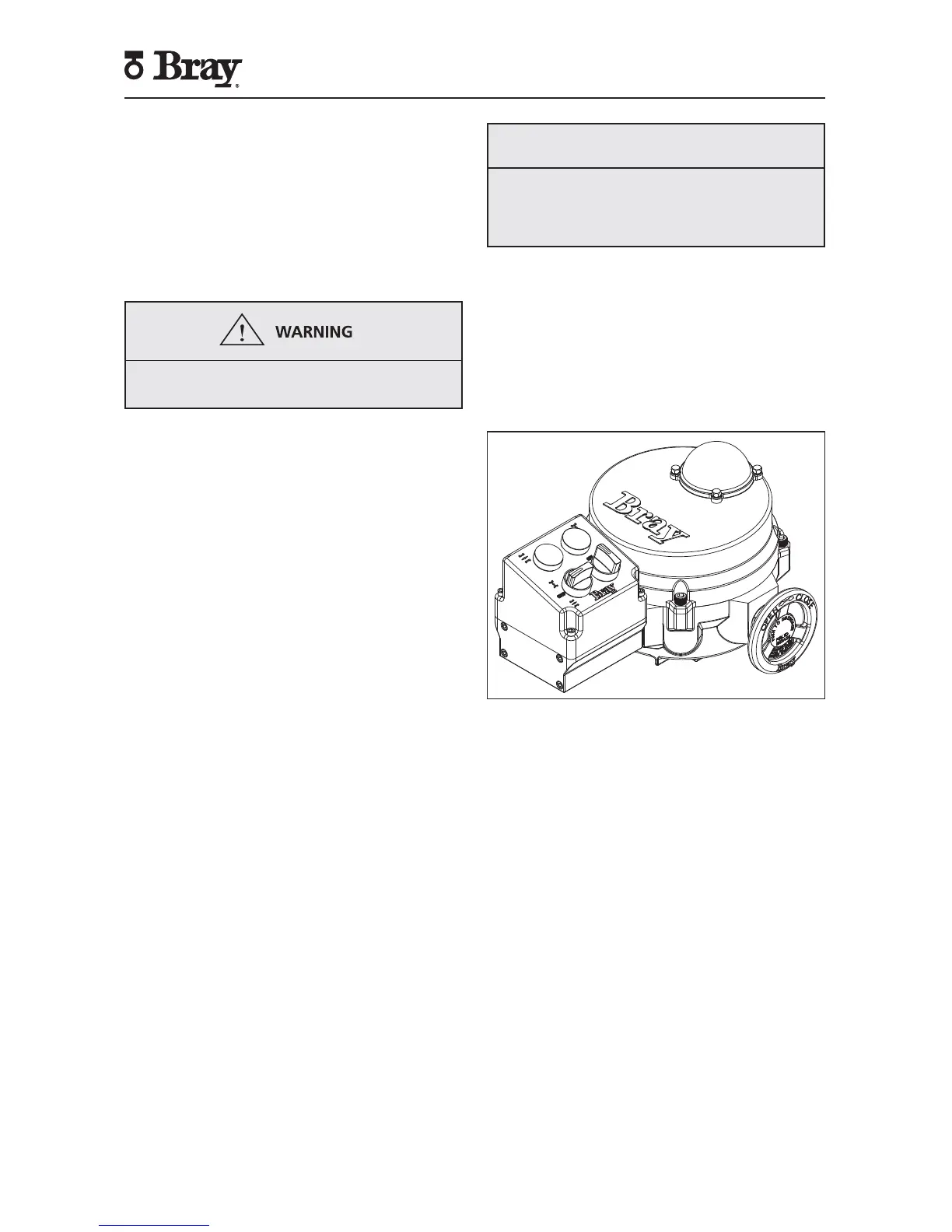
Local Control Station
The local control station is a field or factory installable
option that gives the operator the ability to locally drive
the Series 70 actuator with electrical power; overriding
the control signal from the process controller. The
control station has a red (closed) and green (open)
light to provide end-of-travel indication. It also has two
3-position switches as shown in Figure 17.
Figure 17. S70 with Control Station.
Switch 1 lets the operator choose between the following
three modes of operation:
1. Local: In this mode, using switch 2 the operator
can drive the actuator to open or close position,
or stop the actuator; overriding any control signal
from the process controller.
2. Off: In this mode, the actuator can only be operated
manually.
3. Remote: In this mode, the actuator is controlled
remotely from a process controller.
Control Station Kit
• Local Control Station Assembly
• #10-24UNC x 4.5” Socket Head Cap Screws
(Qty:4)
• O-rings (Qty:4)
• Gasket
• Wiring Diagram
Tools Required:
• Screwdriver, 3/16”[5 mm] tip flat blade
• Screwdriver, No.1 Phillips
• Hex Key, 5/32”
 Loading...