15
Battery Backup Unit (BBU) — Installation & Maintenance Manual Continued
4.6 Wire the Power Supply and Command Signal Generator according the wiring diagram specific to
your model. Power Supply and Command Signal Generator shall not be powered on yet.
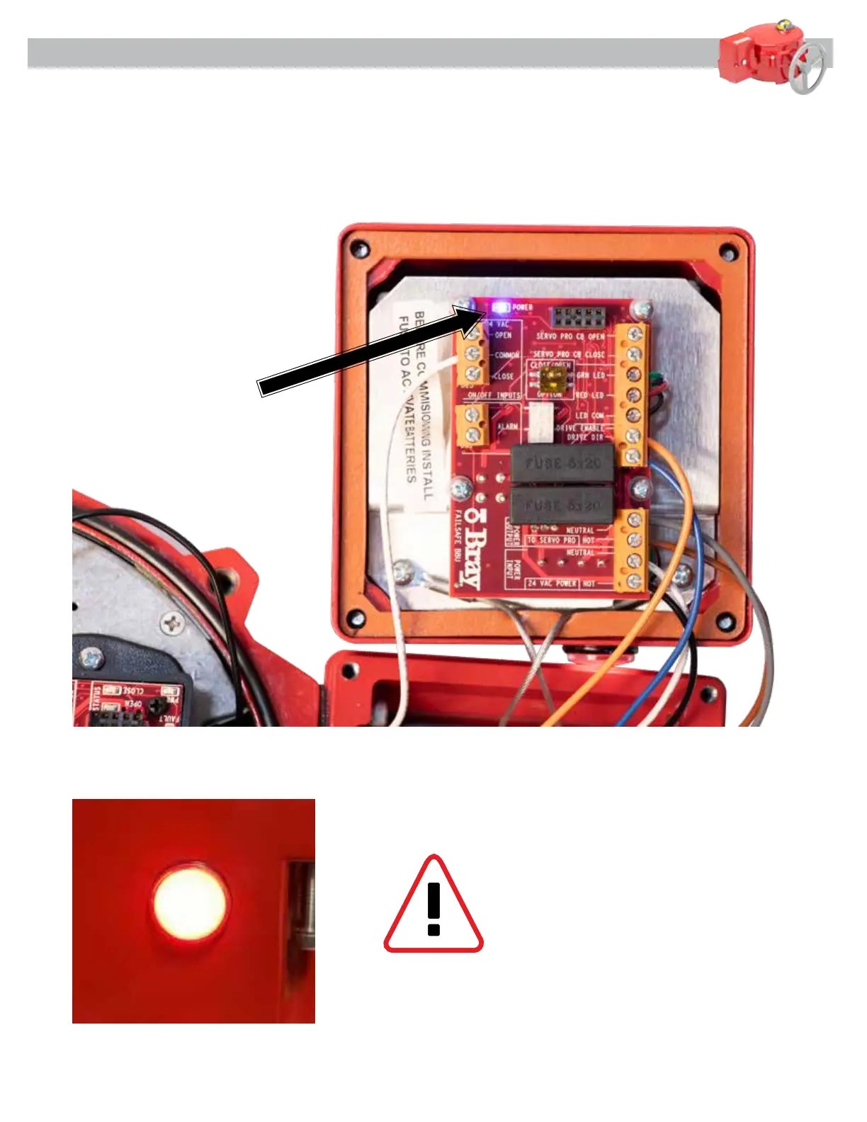
4.7 Insert the fuse supplied under the white label. See [Figure 13] below. Verify LED indicator on the
side of the BBU is flashing RED and the Power LED on the BBU Circuit Board is on.
Figure 13
WARNING – ONCE BATTERY POWER
IS APPLIED TO THE BBU, THE UNIT IS
OPERATIONAL AND MAY CAUSE THE
ACTUATOR TO SEEK THE FAIL POSITION
IF THE MAIN POWER IS NOT CONNECTED
TO THE BBU.