C
Chris TannerSep 9, 2025
Why do my Brecknell 67XXU Scales display '____'?
- KKatie LittleSep 9, 2025
This display means the weight reading is below the Under load limit. Install the platform on the scale and perform a zero calibration.
Why do my Brecknell 67XXU Scales display '____'?
This display means the weight reading is below the Under load limit. Install the platform on the scale and perform a zero calibration.
Why can't I display weight in my desired unit on Brecknell 67XXU?
This issue occurs when the desired unit is not enabled, or d?5oz when the unit is lb:oz. To resolve this, enable the unit in CONFG-UNITS.
What does 'PWT.ER' mean on Brecknell 67XXU?
The 'PWT.ER' error means the piece weight is too small (less than 0.5d), indicating that the weight on the platform is insufficient to define a valid reference weight. Use a greater weight for the sample.
What does 'PCT.ER' mean on my Brecknell Scales?
The 'PCT.ER' error means the unit-percentage weight is too small. Specifically, the weight of 1%, 0.1%, or 0.01% (determined by CONFG-FUNC-PERCNT) is less than 0.5d. To resolve this, use more weight for the sample.
What does 'STB.ER' mean on Brecknell Scales?
Explains manual structure and text conventions used within the document.
Details how keys and displayed messages are represented in the manual.
Defines special symbols like CAUTION, WARNING, and NOTE used in the manual.
Lists operational warnings, including environmental and interference factors.
Emphasizes the need for regular checks and calibration for proper operation and safety.
Advises against using sharp objects to operate keys to prevent damage.
Provides DOs and DON'Ts for cleaning the scale indicator safely and effectively.
Indicates the status of CE certification for the product.
Critical safety warning regarding electrical shock when opening the unit.
Step-by-step instructions for unpacking the scale and its components.
Instructs to remove a specific screw from the scale base before use.
Guides users to connect all required cables to their respective connectors.
Explains how to level the scale using its adjustable feet and bubble level.
Details the scale's connectors for power, USB, and RS-232 serial ports.
Notes that the indicator display can be removed for remote mounting.
Explains how to connect the AC to DC power adapter and voltage polarity check.
Describes the USB connector's function as a virtual RS-232 port and power supply.
Details the bi-directional RS-232 serial port for PC or printer connection.
Explains how to detach and mount the indicator display remotely on a desk or wall.
Shows the main board and identifies connectors for loadcell, RS-232, USB, and power.
Details the pinouts and electrical levels for Loadcell and Adapter Power Input connectors.
Provides pin definitions for USB and RS-232 connectors, plus CAL Jumper set.
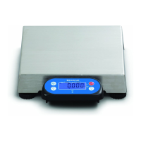
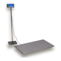
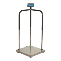
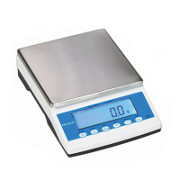
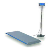
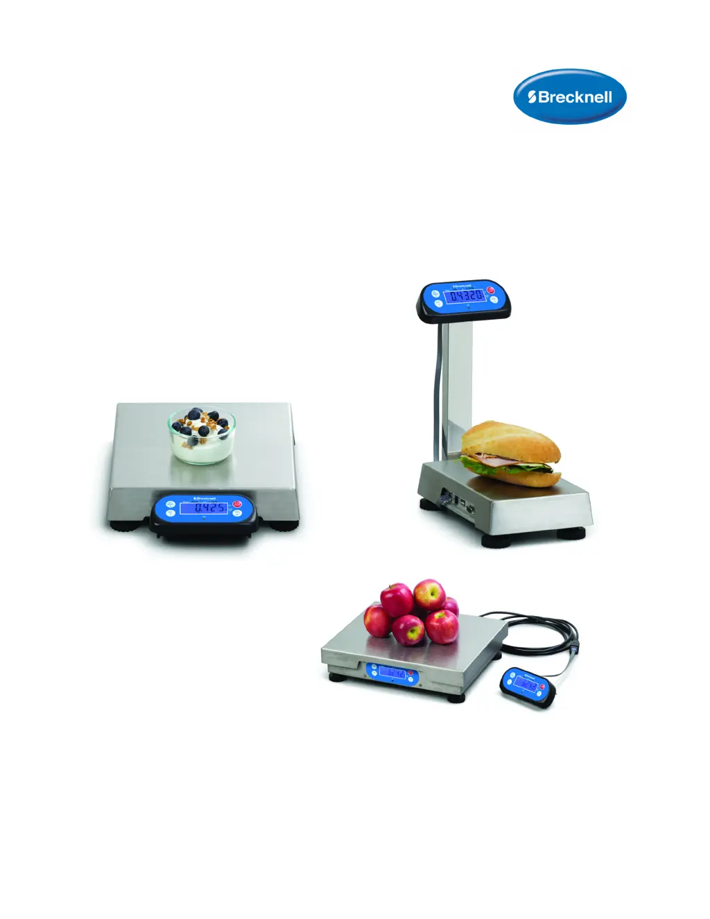
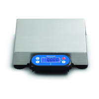
Lists the different models of the 67XXU scale with their platform sizes and capacities.
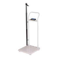
Provides detailed dimension drawings of the scale, including with an indicator on a column.
Covers mounting options, power supply, display, environment, load cell, and approvals.
Details communication specs, analog circuitry, capacity, accuracy, and calibration methods.
Lists various functions like programmable zero range, tare, auto-power off, and counting mode.
Describes the front panel layout, keypad, and the meaning of LCD display annunciators.
Details the functions of the four keys and their multi-functionality based on mode and press duration.
Explains how to navigate and operate the scale in the weigh mode.
Details how to perform Zero, Tare, Preset Tare, and Clear Tare functions.
Covers outputting data, changing units, and using the weight comparison feature.
Provides tables showing display division values for kg and lb primary units.
Describes how to enter and operate the scale in counting mode.
Steps to enter counting mode and use available keys for operations.
Details two methods for obtaining piece weight: direct input or sample weighing.
Explains how to use the Hold function to freeze displayed numbers, including A/D converter speed.
Specifies required menu settings, access, and lists various hold methods.
Provides in-depth explanations for Positive Peak, Negative Peak, Toggle, Average, and Auto HOLD modes.
Covers displaying versions, performing display tests, and testing keys/buzzer.
Explains how to test serial port receiving and transmitting capabilities.
Guides on how to enter, navigate, and select options within the setup menu.
Introduces detailed descriptions of setup menu parameters.
Illustrates the CONFG menu structure and parameter choices.
Explains CONFG menu parameters like RESET, REGUL, PRIM.N, PRIM.D.
Explains CONFG menu parameters like PRIM.Ut, SECD.N, 10.DSP, MOTION, OVER.D, UNITS.
Explains CONFG menu parameters related to Zero Point, Filter, and Functions.
Covers CONFG menu parameters for HOLD, COUNT, COMPR, GE.CAL, WT.ADJ.
Introduces the USER menu structure and its parameter choices.
Explains USER menu parameters for COM1 (USB) port settings like baud rate and byte format.
Details USER menu parameters for COM1 content, format, and output modes.
Covers USER menu parameters for COM1 scale ID, gross/net weight, and units.
Explains USER menu parameters for COM2 port settings like baud rate and byte format.
Details USER menu parameters for COM2 content, format, and output modes.
Covers USER menu parameters for COM2 scale ID, gross/net weight, and units.
Explains USER menu parameters for beep settings based on key presses and limitations.
Details USER menu parameters for Hold function, including A/D speed, hold mode, and timing.
Covers USER menu parameters for no hold range, command source, status bits, auto-off, and LCD backlight.
Introduces the CAL menu structure for scale calibration.
Explains CAL menu options like seal switch position and zero point calibration.
Details CAL menu parameters for line calibration, geographical position, and gravity value.
Introduces the MISC menu for displaying A/D counts, voltage, and firmware version.
Introduces the TEST menu for performing LCD, COM, and key tests.
Provides instructions on how to exit the setup menu and return to normal operation.
Guides on how to enter the calibration mode and view calibration counters.
Details the procedure for performing zero point calibration on the scale.
Explains the process of performing linearity calibration with multiple weight points.
Covers how to perform geographical adjustment and input gravity value.
Guides on inputting or viewing calibration parameter values.
Explains how to adjust displayed weight without a standard weight, within limits.
Details how to examine ADC output code for system stability and calibration.
Guides on configuring COM port settings like baud rate, byte format, and protocol.
Describes COM ports, protocol basics, and transaction string structure.
Introduces commands and responses for scale communication.
Explains commands and responses for the NCI-SCP01 protocol.
Summarizes commands like W, S, Z, T, U, L, X for NCI-SCP01 protocol.
Details commands and responses for the ECR-SCP02 protocol.
Summarizes commands like W, S, Z for the ECR-SCP02 protocol.
Continues command summaries for ECR-SCP02, including u, A, m commands.
Summarizes commands like ENQ, L, X for ECR-SCP02 protocol.
Details commands and responses for the 8213-SCP03 protocol.
Summarizes commands like W, Z for 8213-SCP03 protocol and their responses.
Summarizes commands like H, A, B, E for 8213-SCP03 protocol.
Summarizes command F for 8213-SCP03 protocol and other unrecognized commands.
Details commands and output string frames for the MULTI parameter.
Shows example data outputs for Weighing and Counting modes using MULTI parameter.
Details commands and responses for EH-SCP (PS-60) protocol.
Summarizes commands like W, S, Z, T, X for EH-SCP protocol.
Details commands and responses for the IBM protocol.
Summarizes commands like W, Z for IBM protocol.
Explains the purpose and location of the physical seal for legal for trade configurations.
Introduces audit trail parameters for tracking changes and calibration.
Guides on how to view configuration and calibration counters.
Lists ASCII characters and their corresponding LCD/LED representations.
Explains the meaning of various symbols and abbreviations displayed on the scale.
Provides a table of common symptoms, probable causes, and remedies.
Continues the table of common error messages and their troubleshooting steps.
Further lists error messages related to units, hold function, power, and zeroing.