7
INSTALLATION
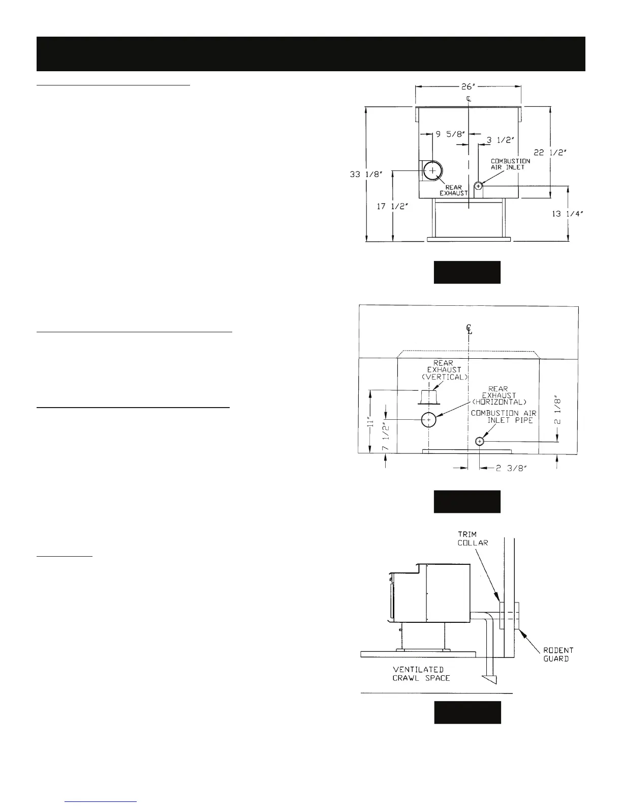
REAR VIEW P24FSA
FIGURE 5
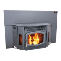
REAR VIEW P24I
FIGURE 6
FIGURE 7
COMBUSTION AIR SUPPLY
For a mobile home installation the stove must be connected to an outside
source of combustion air. A 2” inside diameter metallic pipe, either exible
or rigid, may be attached to the inlet at the stove’s rear (refer to gures 5 &
6). A rodent guard (minimum ¼” wire mesh)/wind hood must be used at
the terminus (refer to gure 7). All connections must be secured and air-
tight by either using the appropriately sized hose clamp and/or UL-181-AP
foil tape.
For mobile home installations only: 2” inside diameter pipe may be used
for the rst 5 feet of combustion air supply run. From 5 to 10 feet use 2 ¾”
inside diameter pipe. No combustion air supply may exceed 10 feet.
Sources of Outside Combustion Air
a. In replaces
• Chimney top.
• Ash clean out door.
b. For freestanding installations
• A hole in oor near stove rear terminating only in a ventilatcrawl
space.
• A hole in the wall behind the stove.
WHEN OUTSIDE AIR IS NOT USED
If outside air is not used, it is important that combustion air is easily avail-
able to the air inlet. A closeable outside air register can be used in tightly in-
sulated homes. In insert installations, ashing vents should not be restricted.
e ashing should not necessarily seal the replace face.
IMPORTANCE OF PROPER DRAFT
Dra is the force which moves air from the appliance up through the
chimney. e amount of dra in your chimney depends on the length of the
chimney, local geography, nearby obstructions and other factors. Too much
dra may cause excessive temperatures in the appliance. Inadequate dra
may cause backpu ng into the room and ‘plugging’ of the chimney. Inad-
equate dra will cause the appliance to leak smoke into the room through
appliance and chimney connector joints.
An uncontrollable burn or excessive temperature indicates excessive dra .
Take into account the chimney’s location to insure it is not too close to
neighbors or in a valley which may cause unhealthy or nuisance conditions.
VENTING
e Breckwell P24 Freestanding is certi ed for use with listed TYPE L-Vent,
3” or 4” diameter in size. e stove was tested with Simpson Duravent
brand. Class “A” chimney is not required. Refer to the instructions provided
by the vent manufacturer, especially when passing through a wall, ceiling or
roof.
is is a pressurized exhaust system. All vent connector joints must be
sealed with 500°F (260°C) RTV silicone sealant to ensure consistent perfor-
mance and avoid smoke spillage. All horizontal connector joints must be
sealed with UL-181-AP foil tape. We recommend that all vertical vent con-
nector joints be secured with a minimum of 3 screws.
It is strongly recommended that you have a minimum of 6’ of vertical pipe
in your exhaust system. For best performance of the stove limit the number
of elbows and horizontal pipe as much as possible
DO NOT CONNECT THIS UNIT TO A CHIMNEY FLUE SERVING
ANOTHER APPLIANCE. DO NOT INSTALL A FLUE DAMPER IN THE EXHAUST VENTING SYSTEM OF THIS UNIT. INSTALL
VENT AT CLEARANCES SPECIFIED BY THE VENT MANUFACTURER.