8 BRIGGSandSTRATTON.COM
System Setup
You must perform the following before operating the system:
• If generator is installed in an area regularly subjected
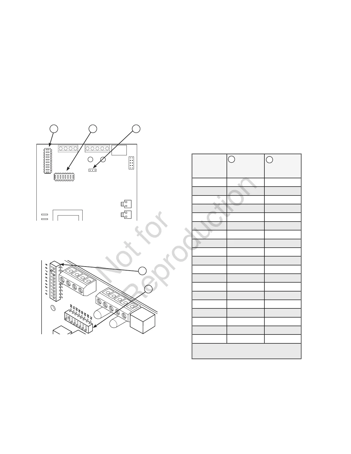
to temperatures below 40°F (4°C), select a 50 second
warm up time by moving jumper JP2 (C) installed
on transfer switch control board from ‘20’ position to
‘50’ position.
• Set the DPSW1 (A) and DPSW2 (B) dipswitches on
the transfer switch control board to match the kW
rating of the home standby generator, as described in
Setting Dipswitches.
Setting Dipswitches
Dipswitches are used to adjust control board operation
based on generator capacity. DPSW1 and DPSW2 switches
are set to correspond to total system kW rating. Dipswitch
DPSW1 (A) has units of 1,000 watts; Dipswitch DPSW2 (B)
has units of 10,000 watts.
Set dipswitches with power removed from the transfer switch
to ensure proper control system operation. If dipswitches are
set when power is present at transfer switch, a power reset
needs to be performed before the new dipswitch settings will
take effect. Power reset is when all power is removed from
the transfer switch and then reintroduced after 30 seconds.
NOTICE A transfer switch fault message will occur on
standby generator control board if dipswitches are not
properly established as noted above.
NOTICE Use extreme caution when setting dipswitches or
damage to control board will result.
• Use a pencil or small piece of plastic to set the dipswitch.
• NEVER use a screwdriver or any type of metal object to set
dipswitches.
To properly establish the dipswitches, make sure that only
one dipswitch is set to “ON” position for DPSW1 and one
dipswitch for DPSW2. For example a 20kW generator, set
DPSW2 dipswitch 20 to “ON” position and DPSW1 dipswitch
0 to “ON” position. 20,000 plus 0 equal 20,000 watts.
The “On” position for the dipswitches is the switch number ON
THE TRANSFER SWITCH CONTROL BOARD, not on the
switch. For example, for an 18,000 watt generator, set DPSW2
dipswitch 10 to “On” position. Set DPSW1 dipswitch 8 to “On”
position. 10,000 plus 8000 equals 18,000 watts.
Set only one
switch to “On” position on DPSW1 and DPSW2.
Refer to following chart for proper switch selection(s).
NOTICE
Air density is less at high altitudes, resulting in
less available engine power. Specifically, engine power will
decrease 3.5% for each 1,000 feet (300 meters) above sea
level and 1% for each 10° F (5.6°C) above 77°F (25°C).
Generators located in these conditions must have the transfer
switch programmed appropriately for this power decrease.
CT1
CT2
DPSW2
DPSW1
J6
CA B
A
B
kW Rating
of
Generator
DPSW
#1 “ON”
Position
DPSW
#2 “ON”
Position
7kW 7 0
8kW 8 0
9kW 9 0
10kW* 0 10
11kW* 1 10
12kW 2 10
13kW* 3 10
14kW 4 10
15kW 5 10
16kW 6 10
17kW 7 10
18kW 8 10
19kW 9 10
20kW 0 20
30kW 0 30
45kW 5 40
48kW 8 40
50kW 0 50
60kW 0 60
* For generators with a rating that includes 500 Watts,
round down to next lowest rating
(example: 13.5 kW set to 13kW)
A
B
 Loading...