9
Supervisory Control Wiring (Use Only
with 6421 Kit)
An air conditioner can be used with the supervisory
contacts on either terminals A-A or B-B. Terminals A-A
can only be used with supervisory control. Large loads
can only be used with contactor control on terminals
B-B. Examples of each system are described below.
1. The terminal strip on control module in transfer
switch has four connections for customer
use. There are two sets of “Normally Closed”
contacts available. They will be activated when
generator power is required. These can be used
for supervisory control of large connected loads
on generator. Loads will be allowed to operate if
there is enough generator power available.
NOTE: There are two wireways provided to keep the
supervisory loads separated from each other.
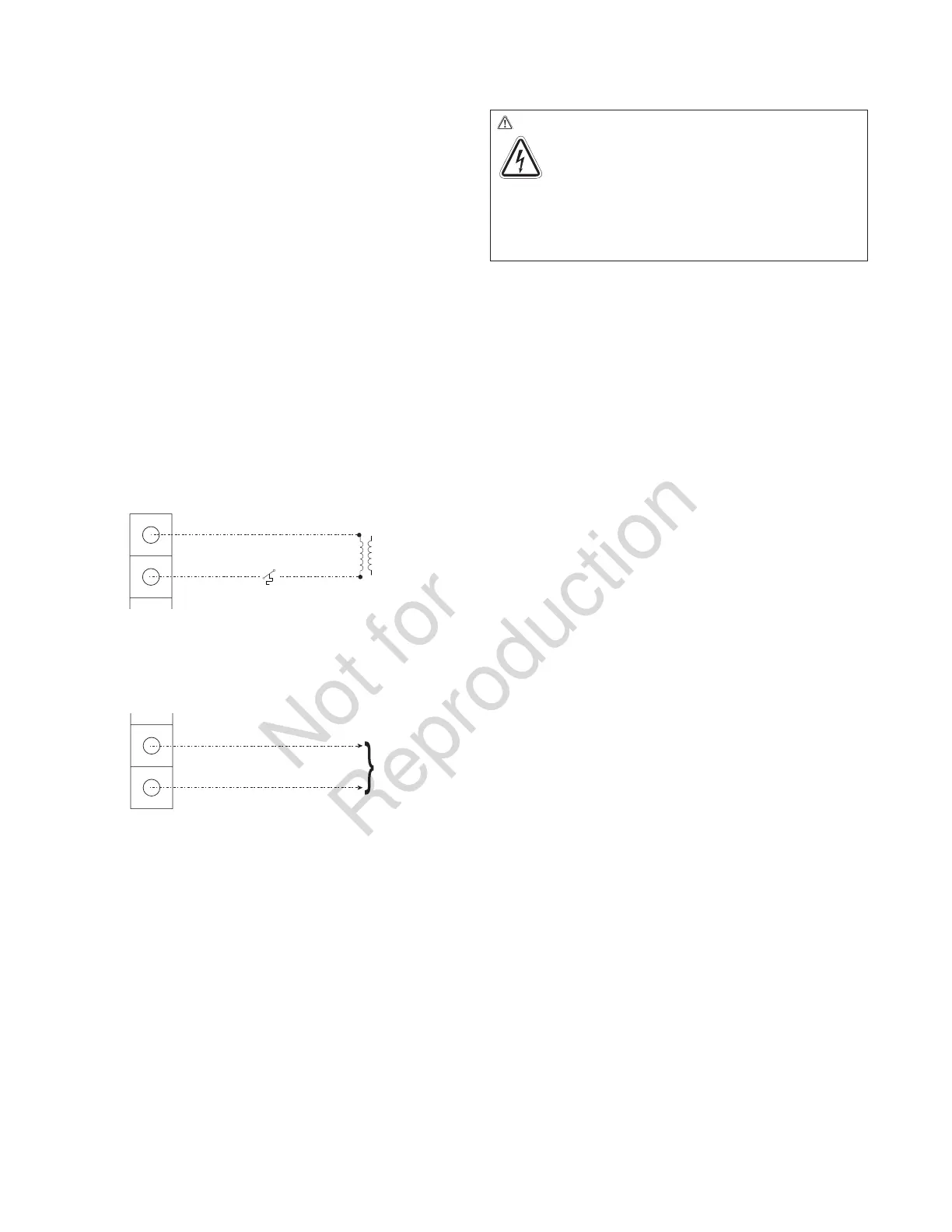
2. Terminals “A-A” on control module are rated for
24 VAC and air conditioner contactor control.
Contacts are connected in series with the air
conditioner contactor control circuit.
3. Terminals “B-B” on control module are rated for
1 Amp 125 VAC and installer supplied contactor
to control a large load, such as an electric hot
water heater. Contacts are connected in series
with the contactor control circuit.
4. Tighten all wire connections/fasteners to proper
torque. See label inside transfer switch enclosure
for proper torque values.
Testing the Automatic Transfer Switch
Turn the utility service disconnect circuit breaker feeding the
transfer switch contactor to the OFF position. The system’s
automatic sequence described below will initiate. To return to
utility power, turn the utility service disconnect circuit breaker
to the ON position.
Utility Fail
The generator senses when utility voltage is below
70 percent of nominal. Engine start sequence is initiated after
6 second time delay.
Engine Warm-Up
Time delay to allow for engine warm-up before transfer. Use
jumper on transfer switch control board to select delay of
20 seconds or 50 seconds.
Transfer
Transfer from utility to generator supply occurs after voltage
is above set levels. The transfer switch control board LED
lights will change from green (utility) to red (generator)
and the Symphony II status light will change blink status
from Blink Blink_Pause_Blink Blink to Blink_Pause_Blink.
Minimum engine run time is 5 minutes after transfer.
Utility Pickup
Voltage pickup level is 80 percent of nominal voltage.
Retransfer
Retransfer from generator to utility power is approximately 10
seconds after utility voltage supply is above pickup level and
minimum run time is completed. All remote module(s) will
remain OFF for five minutes after the power transfer.
Engine Cool Down
Engine will run for 60 seconds after retransfer.
WARNING Shock Hazard. Equipment contains high
voltage that could cause electrocution resulting in
death or serious injury.
• Testing must only be performed by qualified personnel.
• Do not operate this equipment imprudently, carelessly or
neglect its maintenance.
A
A
Air Conditioner Contactor
24 VAC
B
B
Contactor
Neutral
120 VAC
 Loading...