Page | 19
Alarms
5
An alarm condition occurs when a preconfigured parameter is outside of a pre-set level. On initiation of
an alarm, the Alarm LED will start blinking and the fault output pin will be activated if configured. The
controller will display the name of the alarms along with a count on the ALARMS screen and the nature
of alarm on the ENGINE STATUS screen. For acknowledging and clearing the alarms, press the “UP +
DOWN” keys simultaneously. Alarms are ignored until the end of the Safety Monitoring Start Delay
duration. The controller will not issue the start command if the Shutdown Alarm is left unacknowledged.
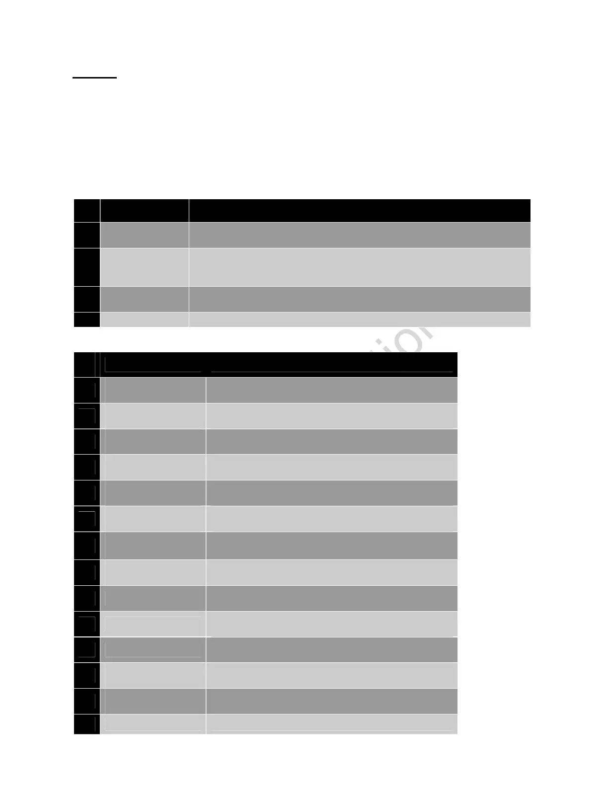
Table 5 shows the types of alarm actions whereas Table 6 shows types of alarms. Please refer to Table
5 and Table 6.
Table 5: Alarm actions
# Alarm Actions Description
1
Notification
Controller will display message on the display screen, and this will not affect
the genset start stop operation.
2
Warning
Warning alarms serves to draw operator's attention to an undesirable condition
without affecting genset's operation in genset ON condition.
The genset cannot be started without acknowledging the warning alarms.
3
Electrical trip
In this alarm action type the engine cool down timer begins, after which the
genset is stopped.
4
Shutdown In this alarm the genset is immediately stopped.
Table 6: Alarms and their causes
Sr.
No.
Alarms Causes
1
Low Oil Pressure
Sensor
Indicates that the oil pressure measured is below the pre-
set threshold
2
Low Oil Pressure
Switch
Indicates that the oil pressure measured is below the pre-
set threshold
3
High Oil Pressure
Sensor
Indicates that the oil pressure measured is above the pre-
set threshold
4
High Oil Pressure
Switch
Indicates that the oil pressure measured is above the pre-
set threshold
5
High Engine
Temperature sensor
Indicates that the engine temperature is above the pre-set
threshold
6
High Engine
Temperature switch
Indicates that the engine temperature is above the pre-set
threshold
7
Anlg LOP (Pin 26) Ckt
Open
The oil pressure sensor is detected as not being present
8
Amb Temp (Pin 24)
Ckt Open
The temperature sensor is detected as not being present
9 Emergency Stop
Configured as digital input has triggered longer than pre-
set duration or when the immediate shutdown is required
10
Fail To Stop
Indicates that genset has not stopped after sending Stop
command
11
Fail To Start
Indicates that genset has not started after the pre-set
number of Start attempts
12
R/L1 Phase Over
Voltage
Indicates that genset L1(R) Phase voltage has exceeded
the pre-set over voltage threshold.
13
Y/L2 Phase Over
Voltage
Indicates that genset L2(Y) Phase voltage has exceeded
the pre-set over voltage threshold
14
B / L3 Phase Over Indicates that genset L3(B) Phase voltage has exceeded
 Loading...