16
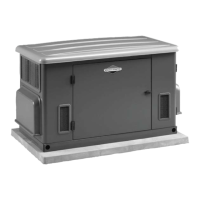
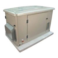
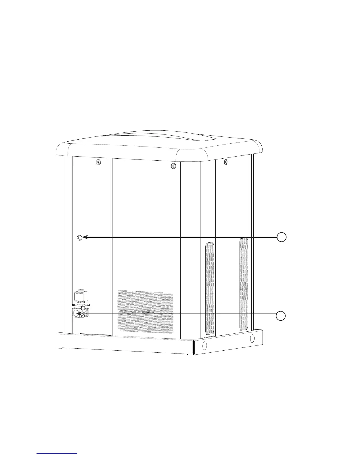
Electrical and Fuel Inlet Locations
The 3/4 inch N.P.T. fuel inlet connector (A) and electrical inlet
location (B) is shown below.
A ½ inch knock-out is provided for the electrical inlet. This
inlet may be enlarged or supplemented to accommodate a
maximum conduit size of 1 ½ inches.
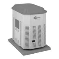
The generator is supplied with a base that, unless mandated
by local code, does not require a concrete slab.
A
B
 Loading...