13
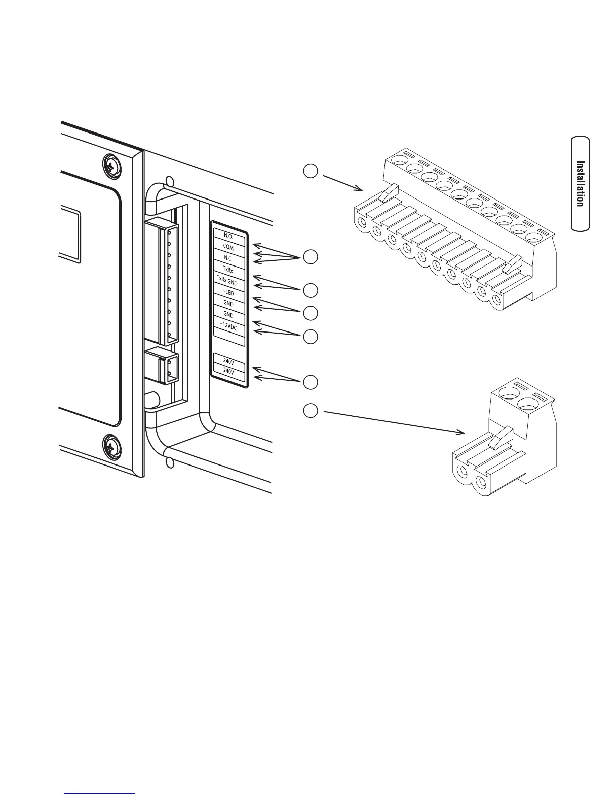
System Connectors
Except for the power output and grounding connectors, all signal wire connections are made to removable two- or ten-pin
connector plugs. Compare this illustration with your generator to familiarize yourself with the location of these important
connections:
A - 10 Pole Connector Plug
B - Fault Contacts — Use NO, COM and NC to hook up a
siren, light, optional GenAlert, etc. to alert you in case
of a fault. Contacts reverse state (NO goes to NC and
vice versa) upon a fault condition.
C - Transfer Switch Communication — Use TxRx and TxRx
GND to transfer switch to monitor generator functions.
D - Remote LED Output — Use this to hook up the remote
LED supplied with the generator. The remote LED will
turn on and off in a series of blinks if certain faults are
detected in the generator.
E - +12 Volt DC, .5 Amp Output — Internal power supply.
F - 240 Volt Utility — Use to hook up the 240V utility leads
from the transfer switch to the generator.
G - 2 Pole Connector Plug
B
A
C
D
E
F
G
 Loading...