50
7
7
Check Connecting Rod Bearing Clearances
NOTE: If connecting rod bearings show signs of
flaking or scoring, bearings must be replaced.
NOTE: Connecting rod bearings and crankpin
journals must be clean and free of oil.
1. With upper bearing assembled to the
connecting rod, install the connecting rod.
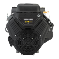
2. Lay a strip of plastigage lengthwise on journal
(A, Figure 7).
NOTE: Do not lay plastigage across hole in
crankshaft journal.
Figure 7
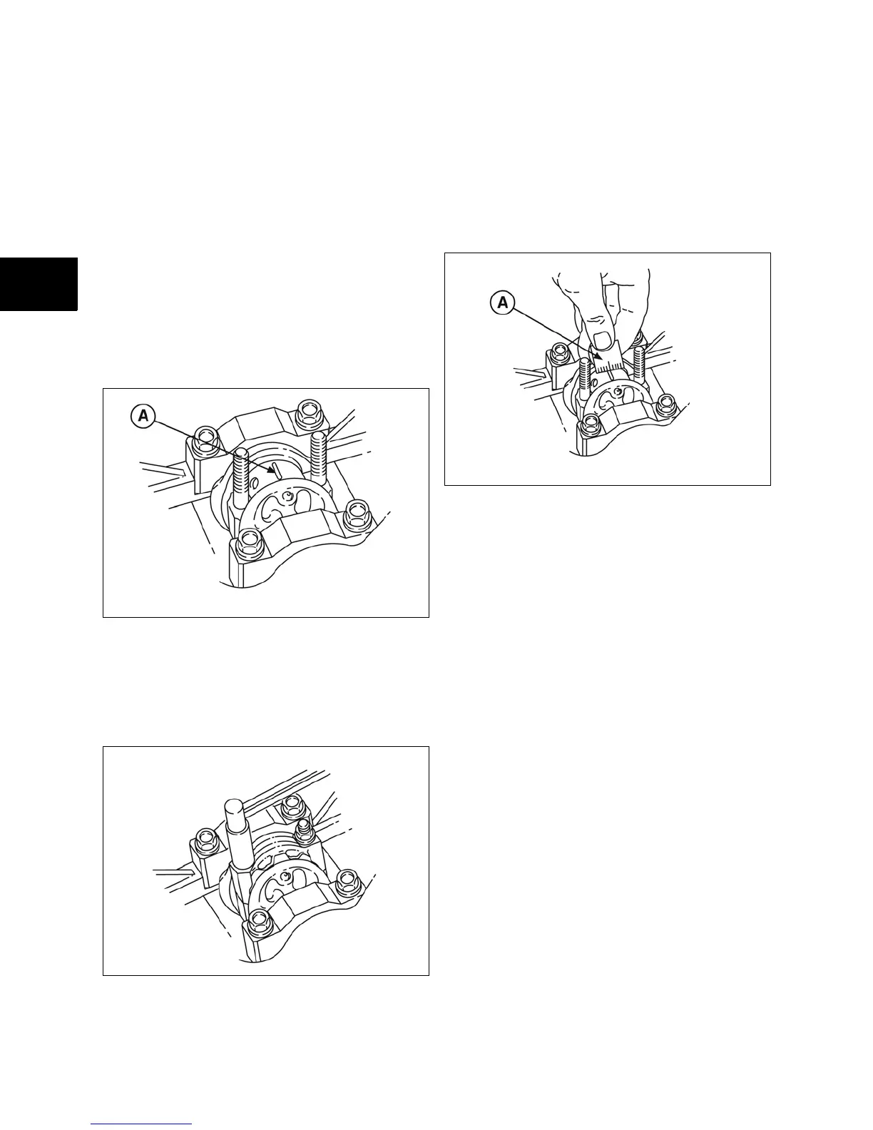
3. Assemble connecting rod cap with bearing
and torque to values listed in Section 14
(Figure 8).
NOTE: Do not allow crankshaft to rotate.
Figure 8
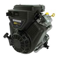
4. Remove the connecting rod cap. Measure the
plastigage at its widest point (A, Figure 9). If
the clearance is not within specification,
replace the bearings.
• Standard Main Bearing Clearance -
0.0008 - 0.0017 in. (0.020 - 0.044 mm)
• Reject Main Bearing Clearance - 0.0028
in. (0.07 mm)
Figure 9
5. Repeat procedure for each main bearing.
Check Crankshaft End Play
1. With thrust washers installed, check
crankshaft end play at #3 main bearing
(Figure 10).
• Standard Crankshaft End Play - 0.0008 -
0.009 in. (0.020 - 0.23 mm)
• Limit Crankshaft End Play - 0.012 in. (0.30
mm)
2. If end play exceeds limit,0.005 in. (0.13 mm),
over size thrust washers are available. See
illustrated parts list for part numbers.
 Loading...