3.4 Calibration 4-20 mA current loop
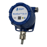
The BlueEye™ Ex-D is factory delivered with a calibrated 4-20 mA current loop. Since actual mA output is
influenced by the (customer specific) current loop system, it is strongly advised to re-calibrate the current
loop once connected to your specific current loop system. This can be done over Modbus, or with Bright
Sensors’ Modbus USB Windows Interface Package.
Please refer to the Modbus manual for details on the registers affiliated with the current loop. To re-calibrate
the current loop via Modbus, please perform the following steps:
• Enable changes to the holding register by entering the passcode 27521 in holding register 50.
• Enter the integer 1 in holding register 32 to override the standard current loop operation.
• Enter an integer between 0 and 4096 in holding register 33. Measure the current loop output of your
current loop system.
• Adjust the input integer (typically 800) in holding register 33 until the measured current equals 4 mA.
Enter the final input integer in holding register 30.
• Adjust the input integer (typically 4000) in holding register 33 until the measured current equals 20
mA. Enter the final input integer in holding register 31.
• Enter the value 0 in holding register 32 to restart the standard current loop operation.
• The current loop has now been calibrated for your system. The calibration values from the steps
above are now visible in input registers 64 and 65, for the 4 mA setpoint and 20 mA setpoint,
respectively.
• Finally, disable further changes to the holding register by saving value 0 to holding register 50.
For details on how to calibrate the current loop using Bright Sensors’ Modbus USB Windows Interface
Package, please consult the GUI (graphical use interface) manual to be found here: https://www.bright-
sensors.com/blueeye-ex-d/.

 Loading...