Side Burner
Igniter Lead
Electrode
27
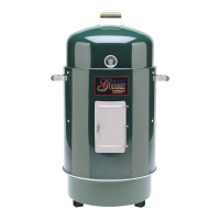
Note: Loosen the pre-attached
bolts on the burner
assembly bracket before
performing Step 12.
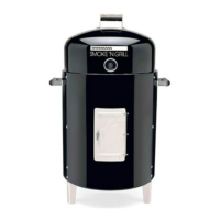
Step 12
Insert the side burner valve
assembly through the holes in the
side burner front panel, then firmly
seat the valve nozzle into the
burner venturi. Rotate burner
valve assembly counterclockwise
to lock in place with keyholes.
Then tighten pre-attached bolts.
Place the side burner control knob
on the side burner valve stem.
Note: Tighten the bolts on the
burner assembly bracket
securely.
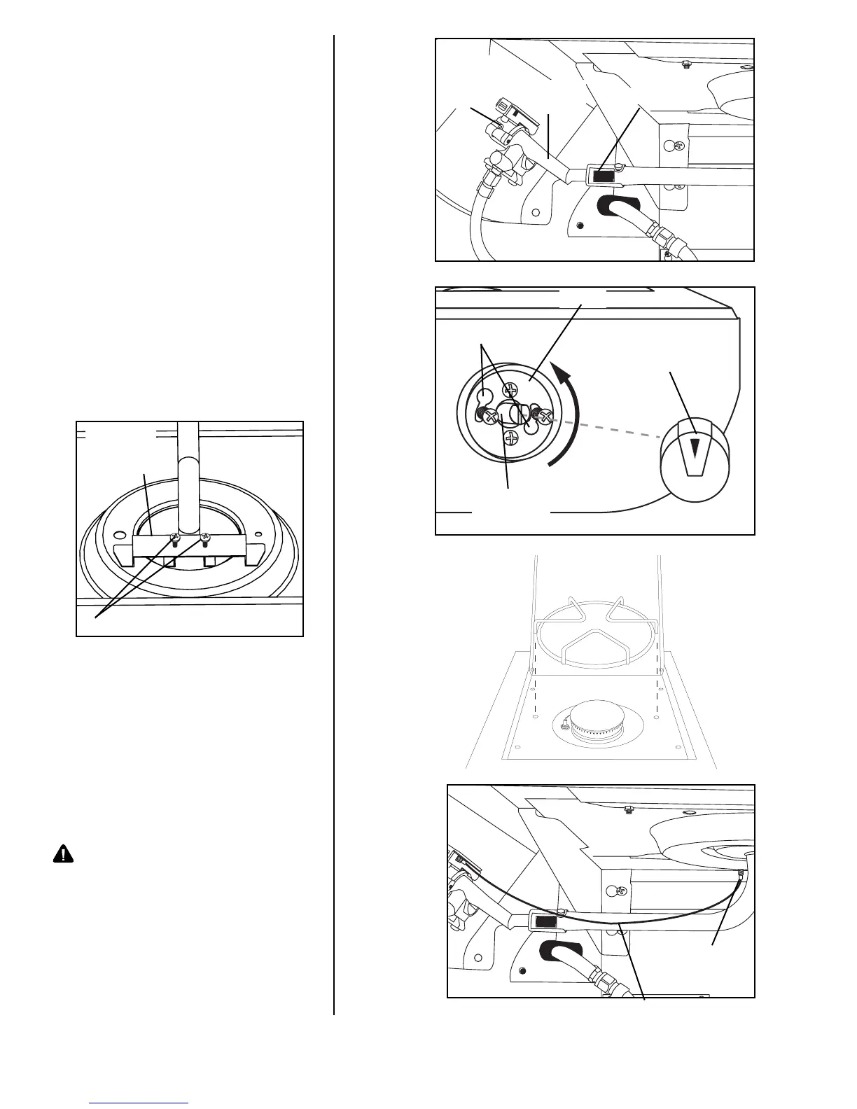
Step 13
Place the side burner grate onto
the side burner table.
Step 14
Attach side burner igniter lead
wire to the electrode as illustrated.
Warning: Never use your grill
without leak testing all
gas connections and
hoses. See the section
on “Leak Testing” in this
manual for proper
procedures.
Side
Burner
Valve
Burner Venturi
Valve
Nozzle
Bezel
Side Burner
Control Knob
Side Burner
Valve Stem
Keyholes
Burner
Assembly
Bracket
Pre-attached Bolts