1018189 Rev. C
8
Step 2a.
9
5/16" Nylon Lock Nut
Qty. 1
32
5/16" Flat Washer
Qty. 2
36
Spring
Qty. 1
38
36
9
32
32
10
3
a) Assemble Lift Handle (3) to Lift Link (14).
Note orientation of Lift Handle (3) to
Lift Link (14) in picture below.
b) Install Hex Bolt (38) as shown. Add
Washer (32) and install handle in middle
hole. NOTE: It may be necessary to put
downward pressure on the Lower Pivot
Assembly (10) to line up the holes.
c) Complete the assembly by adding the
Spring (36), Washer (32), and
Locknut (9). Tighten lock nut, then back
off as necessary for proper operation.
14
38
5/16" x 1-3/4", Hex Bolt
Qty. 1
Step 3.
9
37
37
43
3
35
2
a) Install the Flat Grip (43) to the
Lift Handle (3).
b) Install the Tow Tubes (2) to the
Upper Frame Assembly (35).
9
5/16" Nylon Lock Nut
Qty. 2
37
5/16" x 1-1/2", Hex Bolt
Qty. 2
3
14
================================================================================================
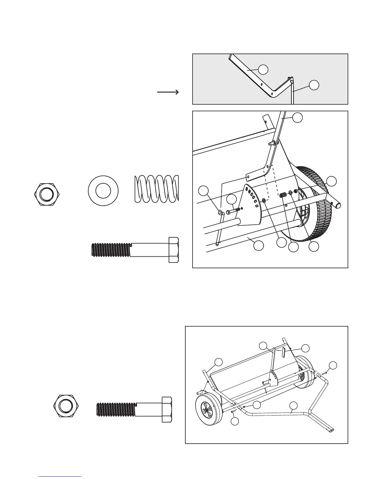
ASSEMBLY
STEP 2-A
--------------------------------------
a)AssembleLiftHandle(3)toLiftLink(14).
Note orientation of Lift Handle (3) to Lift Link (14)
illustrated here.
b)InstallHexBolt(38)asshown.AddWasher(32)andinstall
handle in middle hole. NOTE: It may be necessary to put
downwardpressureontheLowerPivotAssembly(10)to
line up the holes.
c) CompletetheassemblybyaddingtheSpring(36),Washer
(32),and Locknut (9).Tighten locknut, thenback off as
necessary for proper operation.
STEP 3
---------------------------------------------------------------------------------
a. InstalltheFlatGrip(43)totheLiftHandle(3)
b. InstalltheTowTubes(2)totheUpperFrame
Assembly(35).
9
5/16”NylonLockNut
Qty.4
9
5/16”NylonLockNut
Qty.4
32
5/16”FlatWasher
Qty.2
36
Spring
Qty. 1
38
5/16”x1-3/4”,HexBolt
Qty. 1
37
5/16”x1-1/2”,HexBolt
Qty.2
Step 2a.
9
5/16" Nylon Lock Nut
Qty. 1
32
5/16" Flat Washer
Qty. 2
36
Spring
Qty. 1
38
36
9
32
32
10
3
a) Assemble Lift Handle (3) to Lift Link (14).
Note orientation of Lift Handle (3) to
Lift Link (14) in picture below.
b) Install Hex Bolt (38) as shown. Add
Washer (32) and install handle in middle
hole. NOTE: It may be necessary to put
downward pressure on the Lower Pivot
Assembly (10) to line up the holes.
c) Complete the assembly by adding the
Spring (36), Washer (32), and
Locknut (9). Tighten lock nut, then back
off as necessary for proper operation.
14
38
5/16" x 1-3/4", Hex Bolt
Qty. 1
Step 3.
9
37
37
43
3
35
2
a) Install the Flat Grip (43) to the
Lift Handle (3).
b) Install the Tow Tubes (2) to the
Upper Frame Assembly (35).
9
5/16" Nylon Lock Nut
Qty. 2
37
5/16" x 1-1/2", Hex Bolt
Qty. 2
3
14
 Loading...