9
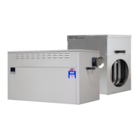
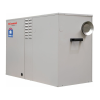
3.5 Installation of Flue Terminal
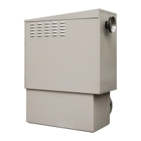
The flue terminal for External models is supplied inside the heater under the roof. On one end of the heater you
will find the flue outlet socket under an installer instruction label.
• Remove the label and insert the flue terminal firmly into the flue outlet socket in the correct orientation to
ensure flue gases are expelled away from the house (see Diagram 9).
Note: The flue terminal must always be installed before starting up the heater.
Diagram 9.
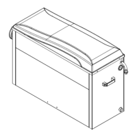
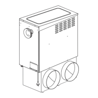
3.6 Area to Cut in the Wall
When installing the heater at ground level, create two holes to suit the pops all the way to ground level (see
Diagram 10), or one rectangular hole to cover the distance of both pops ensuring there is no impediment to the
structural integrity of the dwelling.
Diagram 10.
Note: Refer to heater dimensions to obtain the required dimensions.
3.7 Flue Terminal Clearances
Heaters that are installed outside the house should be positioned so that, when measured from the edges of the flue,
the following minimum clearances exist, which are in accordance with AS 5601:
75mm
• Out from the wall against which it is mounted.
• From a drain or soil pipe.
300mm
• From a flue terminal, cowl or combustion air intake.
• Below eaves, balconies or other projections.
• From the ground, above a balcony or other surface.
• To a return wall or external corner.
• Measured horizontally, from an opening window, door, non-mechanical air inlet or any other opening into the
building (except sub floor ventilation) or 1500mm in direction of discharge.
324702 CAAB024953 StarPro Installers Heat issue D.indd 12 17/05/16 8:41 AM