500mm
• From an electricity meter or fuse box (prohibited area extends to ground level).
1000mm
• Measured vertically, from an opening window, door, non-mechanical air inlet or any other opening into the
building (except sub floor ventilation).
• From a gas meter.
• From a mechanical air inlet, including a spa blower, measured both vertically and horizontally.
• A flue terminal of this type shall not be located under a roofed area, unless the roofed area is fully open on at
least two sides, and a free flow of air at the appliance is achieved.
4. SP4 Model Guidelines
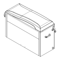
4.1 Heater Dimensions
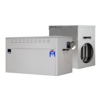
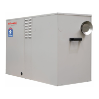
SP4 Universal
Diagram 11.
A
B
C
D
E
øRa
HEATER END PANEL
GAS INLET
FLUE INLET
LOOM MAINS
Dimension
[mm]
A B C D E F G H I J K øSa øRa
SP415UN 625 845 397 14 467 197 447 197 235 95 495 300 300
SP421UN 625 845 397 14 467 197 447 197 235 95 495 300 300
SP430UN 644 923 549 14 487 197 487 237 235 250 515 350 350
SP435UN 644 923 549 14 487 197 487 237 235 250 515 400 400
Note: SP4 Universal is approved for internal or external applications.
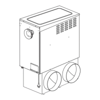
4.2 Internal Installation
Diagram 12. Duct Connection Options