1
1. General Guidelines
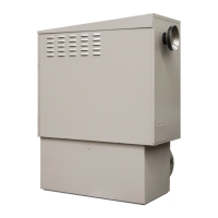
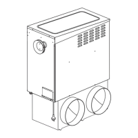
Brivis heaters are designed to provide a central source of heat for a ducted central heating system.
Brivis heaters should not be installed downstream from an air washer, an evaporative cooler or refrigerative
cooling system. Nor are they designed to be installed on a marine craft, houseboat, or any similar environment.
Brivis heaters must be installed in accordance with these i
nstr
uctions and related regulations, codes, standards,
and authorities. These include but may not be limited to:
• AS 5601 - Gas installations • Brivis “SuperSizeGuide”
• AS 4254 - Ductwork for air-handling systems in buildings • Local Building Regulations
• HB 276 • Environment Authorities
• Local Gas and Electricity Authorities • Building Code of Australia (BCA)
Brivis assumes no responsibility for equipment inst
alled i
n violation of any code, regulations
and these installation instructions.
It is recommended the Brivis “SuperSizeGuide” be followed in estimating heating requirements and for system
design that will result in efficient installation and provide a higher level of comfort and economical operation.
For the hourly input and the gas type to be used, see the appliance data label located inside the ser
vice
c
ompartment.
Note: All installations should only be carried out by a qualified tradesperson. Installations at altitudes above
1000m above sea level may require main burner injector upgrading. Please contact the Brivis Customer Service
Centre for advice.
1.1 Inspection
This appliance has been inspected and tested at the time of manufacture and packaging and released for
transportation without known damage. Upon receipt, inspect the exterior for evidence of rough handling in shipment.
Ensure that the appliance is labeled correctly for the gas it is intended to be connected to. Immediately report to Brivis
any discrepancies or damage.
1.2 Unpacking the Heater
Some heaters are supplied on a pallet with a plastic sleeve. To unpack:
• Cut and remove the external plastic packaging and dispose of thoughtfully.
• Remove heater from pallet (if supplied).
Some heaters are supplied with a base box assembly that is wrapped with a plastic film to protect the surface.
Note: Always remove and dispose of the plastic film before mounting the heater onto the base box.
1.3 Unloading or Lifting the Heater
When unloading or lifting the heater, ensure lifting equipment is in good operating condition and capable of lifting
the total load. Be sure there is a clear area to place the heater down, which is within reach of the lifting equipment.
Note: Do not use the lifting handles provided to lift the heater above head height. Instead, secure the heater
with suitable lifting equipment if lifting to elevated heights is required, such as onto a house roof.
1.4 Gas Inlet Connection
• All piping must be in accordance with AS 5601 and any local gas regulations.
• The connection point for external model heaters is a female G3/4 compression fitting to AS 3688 located
on the outer cabinet of the heater.
• The connection point for internal model heaters is a male G3/4 compression fitting to AS 3688 located
in the heater cabinet.
• A gas cock shall be fitted in the gas line adjacent to the heater and in a convenient location so it can be turned
OFF quickly and easily.
• The gas supply should in no way interfere with any servicing of the heater.
Note: The gas supply must be installed by a licensed gas fitter. The gas pipe and gas meter should be sized so
the heater can maintain its required incoming gas pressure at maximum consumption with all other gas
appliances operating at their maximum capacity at the same time as the heater.
1.5 Electrical Power Supply
The heater is pre-wired with a 3-pin plug and lead, and shall be plugged into a standard 10 Amp 220 to 240 volt
fixed switched socket outlet adjacent to the heater, in a convenient location so it can be turned OFF quickly and easily.
Note: A qualified electrician must install the 220 to 240 volt wiring according to local regulations.
 Loading...