Broadcom P411W-32P-UG104
10
P411W-32P PCIe 4.0 User Guide NVMe Switch Adapter
The following table describes the UBM pin settings. For the adapter to properly recognize the backplane, the BP_TYPE pin
must be set to 1. The adapter skips configuration if the BP_TYPE pin is 0, and the firmware logs a message to report that
an unrecognized backplane exists on the connector.
A12 A30 – REFCLK- Output —
B8 B26 0 2W_CLK Input/Output 4.75 kΩ pull-up
B9 B27 1 2W_DATA Input/Output 4.75 kΩ pull-up
B10 B28 2 GND — —
B11 B29 5 PERST# Output 1.0 kΩ pull-up
B12 B30 6 C_TYPE, D_INPL#, CHANGE_DET# Input/Output 10 kΩ pull-up
Table 2 Sideband Management Pin Settings
Pin Name Settings Description
BP_TYPE 0: SGPIO (not supported)
1: 2-Wire
Backplanes must be set to the two-wire interface when using the P411W-32P NVMe
switch adapter. SGPIO is not supported.
2W_RESET#
0: Reset is asserted
1: Reset is not asserted
Optional reset driven by the host if the UBM target reports that the target can be reset.
REFCLK+/- — PCIe REFCLK HCSL 100-MHz clock driven by the device side ports to PCIe devices
that require REFCLK.
If D_INPL# is 0, the adapter enables the REFCLK outputs for that quad of high-speed
lanes.
When the UBM Clock Routing bit on the backplane is 0, this output is turned off.
2W_CLK — The two-wire interface clock signal.
2W_DATA — The two-wire interface data signal.
PERST# 0: Reset is asserted
1: Reset is not asserted
The adapter drives the PCIe RESET# signal.
This signal uses a clamp to ground so that the signal on the adapter powers up LOW
until backplane detection warrants the release of this signal for open-drain use. This
method ensures that PERST# does not deassert until the directly connected NVMe
drive is successfully detected.
C_TYPE,
D_INPL#,
CHANGE_DET#
— Open collector/drain input or output signal.
C_TYPE. Because BP_TYPE is 1, this signal adheres to the SFF-8448
requirement to drive this signal to 1 in response to floating the signal. Because this
signal is an open drain signal, ‘driving’ to 1 is when a pull-up resistor pulls this signal
HIGH.
D_INPL#. Because this signal is an open collector and the adapter floats this signal
HIGH, the backplane pulls this signal to ground to indicate an NVMe device is
connected and a two-wire interface backplane management target might be on the
sideband’s two-wire interface.
CHANGE_DET#. If D_INPL# is 0 and a UBM FRU device is discovered on the
two-wire interface, the UBM FRU data can inform the adapter that the device is
CHANGE_DET# feature capable. The adapter can rely on this signal as the
CHANGE_DET# signal as described in the UBM specification. In this mode, the
UBM controller drives this signal LOW to assert CHANGE_DET#.
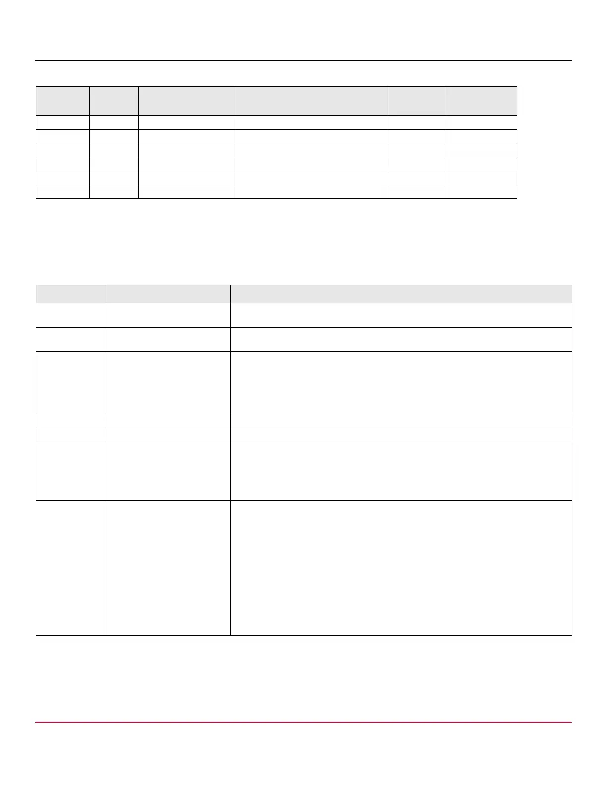
Table 1 Sideband Signal Pinout (Continued)
Connector
A Side
Connector
B Side
Sideband or Vendor
Specific Pin Number
UBM Assignments Direction Resistor Value