Broadcom P411W-32P-UG104
9
P411W-32P PCIe 4.0 User Guide NVMe Switch Adapter
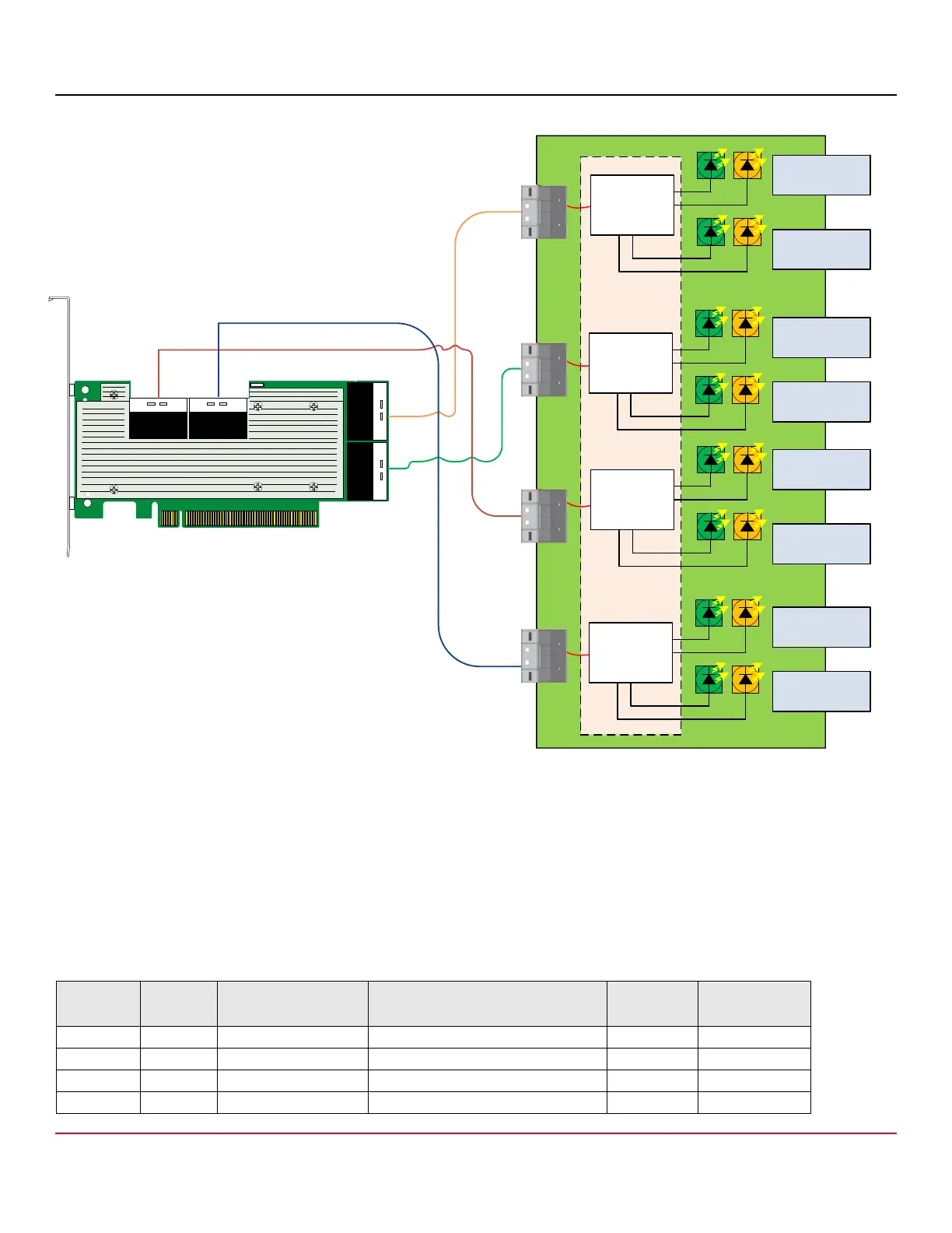
Figure 4 Backplane with x8 Connectors and VPP
5 Sideband Signals
The adapter has four x8 SFF-8654 connectors. Each x8 connector provides two sets of sidebands. This section describes
the sideband signals usage. The following table defines the sideband signal’s pins on the SFF-8654 connector. The last
column in the table indicates the strength of the pull-up resistor or pull-down resistor values on the adapter. See Ta ble 2,
Sideband Management Pin Settings, for the signal descriptions, and see Table 7, Internal Connector Pinout, for a complete
connector pinout.
Table 1 Sideband Signal Pinout
Connector
A Side
Connector
B Side
Sideband or Vendor
Specific Pin Number
UBM Assignments Direction Resistor Value
A8 A26 7 BP_TYPE Input 10 kΩ pull-up
A9 A27 4 2W_RESET# Output 1.0 kΩ pull-up
A10 A28 3 GND — —
A11 A29 + REFCLK+ Output —
?
#
#
##
3&&5
.6-EX$RIVE
3&&5
.6-EX$RIVE
3&&5
.6-EX$RIVE
3&&5
.6-EX$RIVE
!SIDE
0
3LOT
3LOT
3LOT
3LOT
3&&5
.6-EX$RIVE
3&&5
.6-EX$RIVE
3&&5
.6-EX$RIVE
3&&5
.6-EX$RIVE
3LOT
3LOT
3LOT
3LOT
"SIDE
0
0
0
!SIDE
"SIDE
!SIDE
"SIDE
0#!
X
0#!
X
0#!
X
0#!
X