Broadcom P411W-32P-UG104
13
P411W-32P PCIe 4.0 User Guide NVMe Switch Adapter
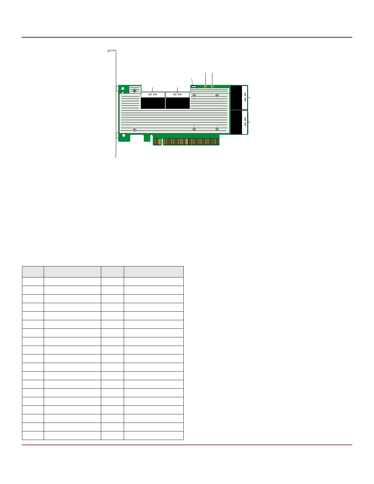
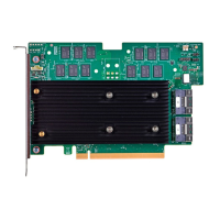
Figure 6 P411W-32P NVMe Switch Adapter Layout
J1, J2, J3, J4 (C0, C1, C2, C3) – x8 SFF-8654 Slimline internal connectors
J22 – UART. Reserved for Broadcom use.
LED11 – SYS_ERROR_N LED
LED12 – Heartbeat LED
J11 – PCIe x16 board edge connector
8.2.1 Connectors
The following table defines the adapter’s internal x8 SFF-8654 SlimSAS connector pinouts. The adapter follows the
SFF-9402 standard for connector sideband signal assignments. Each x8 connector includes eight PCIe transmit and receive
lanes, and two sets of sidebands designated as A and B, in accordance with the SFF-9402 specification.
Table 7 Internal Connector Pinout
Pin Signal Name Pin Signal Name
A1 GND B1 GND
A2 PERp0 B2 PETp0
A3 PERn0 B3 PETn0
A4 GND B4 GND
A5 PERp1 B5 PETp1
A6 PERn1 B6 PETn1
A7 GND B7 GND
A8 BP_TYPEA B8 2W-CLKA
A9 2W_RESETA B9 2W-DATAA
A10 GND B10 GND
A11 REFCLKA+ B11 PERSTA#
A12 REFCLKA- B12 CPRSNTA#
A13 GND B13 GND
A14 PERp2 B14 PETp2
A15 PERn2 B15 PETn2
A16 GND B16 GND
A17 PERp3 B17 PETp3
A18 PERn3 B18 PETn3
A19 GND B19 GND
*
*
*
* *
,%$
*
?
#
#
##
,%$