12
3. CONNECTIONS (CONT’D)
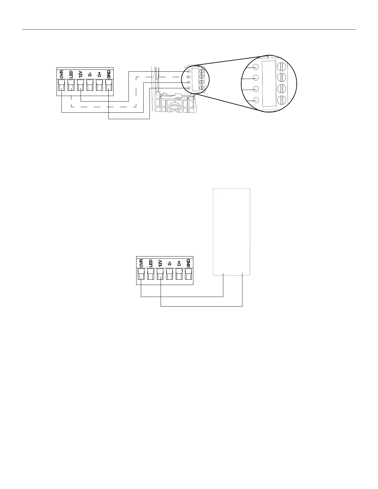
3.2 ELECTRICAL CONNECTION TO OPTIONAL AUXILIARY WALL CONTROL
3.2.1 ELECTRICAL CONNECTION TO 20-40-60 OPTIONAL AUXILIARY WALL CONTROL
Gnd
OVR
12V
LED
VC0243
Gnd
OVR
12V
LED
When confi gurating OVR option on the LCD screen, choose among these 3 confi gurations: BAL (the unit remains balanced while
providing maximum airfl ow), PER (the unit is slightly unbalanced since the distribution motor is in MAX speed while allowing maximum
exhaust ventilation) and DIS (the unit is unbalanced since air distribution is constant despite a higher need in exhaust ventilation).
NOTE : The auxiliary wall control can be used with a 3-wire connection by removing the LED signals. This optional wiring will not allow an
installation with more than 1 auxiliary wall control to properly synchronize their LEDs on an event requested from a peer. Only the
auxiliary wall control having requested the timer event will have the LEDs updated accordingly.
3.2.2 ELECTRICAL CONNECTION TO DRY CONTACT OPTIONAL AUXILIARY WALL CONTROL (E.G. CRANK TIMER)
Crank Timer
or
Any Dry Contact
12VOVR
VC0256