MODEL SPK110
Page 3
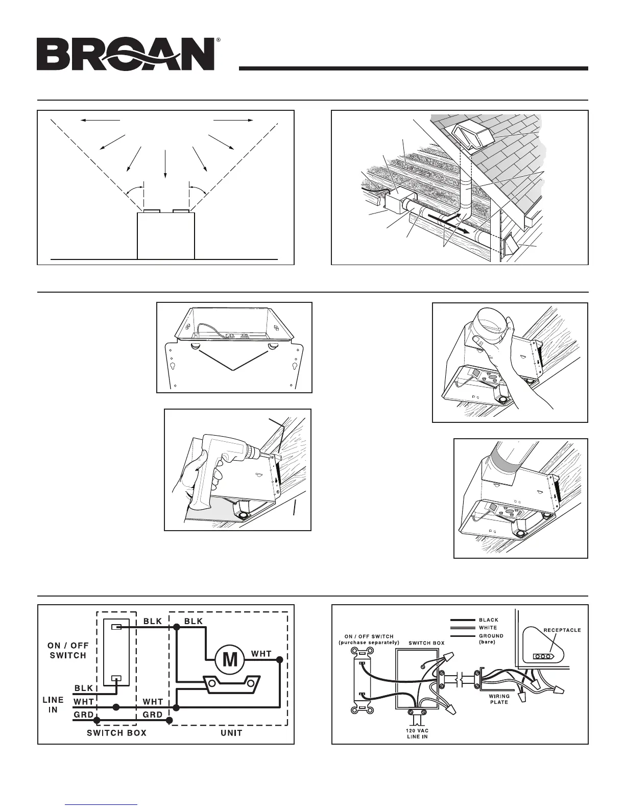
5. Connect electrical wiring. Run 120 VAC house wiring to installation location. Use proper UL approved connector to
secure house wiring to wiring plate. Connect wires as shown in wiring diagrams.
CONNECT WIRING
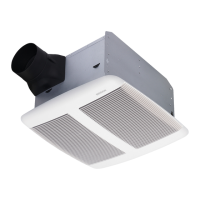
3. Attach
damper/duct
connector.
Snap damper /
duct connector
onto housing.
Make sure con-
nector is flush with
top of housing and
damper flap falls
closed.
4. Install 4-inch
round duct-
work.
Connect 4-inch round
ductwork to damper /
duct connector. Run
ductwork to a roof cap
or wall cap. Tape all
ductwork connections
to make them secure
and air tight.
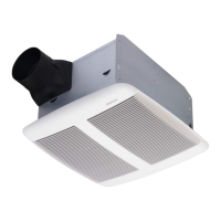
INSTALL HOUSING & DUCT
1. Bend
housing tabs.
Use a pliers to bend
housing TABS out to
90
0
.
2. Mount housing
to joist.
Hold housing in place
so that the housing tabs
contact the bottom of
the joist. The housing
mounts with four (4)
screws or nails. Screw
or nail housing to joist
through lowest holes in
each mounting flange,
then through high-
est holes. NOTE: Mounting to I-JOIST (shown) requires use
of SPACERS (included) between the highest hole of each
mounting flange and the I-joist.
SPACER
(use for mounting to I-Joist)
I-JOIST
TABS
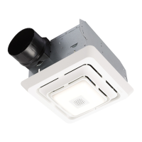
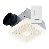
SPEAKER
PLAN THE INSTALLATION
Cooking
Equipment
Floor
Do not install above or
inside this area.
45
o
45
o
NOT FOR USE IN
A COOKING AREA.
ROOF CAP*
(with built-in
damper)
WALL CAP*
(with built-in
damper)
4-IN. ROUND
4-IN. ROUND
DUCT*
FAN
HOUSING
Seal gaps
around
housing.
Seal duct
joints with
tape.
Keep duct
runs short.
INSULATION
(Place around and
over fan housing.)
POWER
CABLE*
*Purchase
separately.
OR
 Loading...