Enable Access Gateway Mode
1. At the terminal application prompt, type SwitchDisable, and press Enter to disable switch mode.
2. If you are converting an Brocade 5100 currently configured as a switch to Access Gateway mode, type configUpload Save
and press Enter to save the current configuration.
3. To enable Access Gateway mode, type ag - -modeEnable, and press Enter. The switch automatically reboots and comes
back online in Access Gateway mode.
4. Enter the ag - -modeShow command to ensure that the Brocade 5100 is in Access Gateway mode.
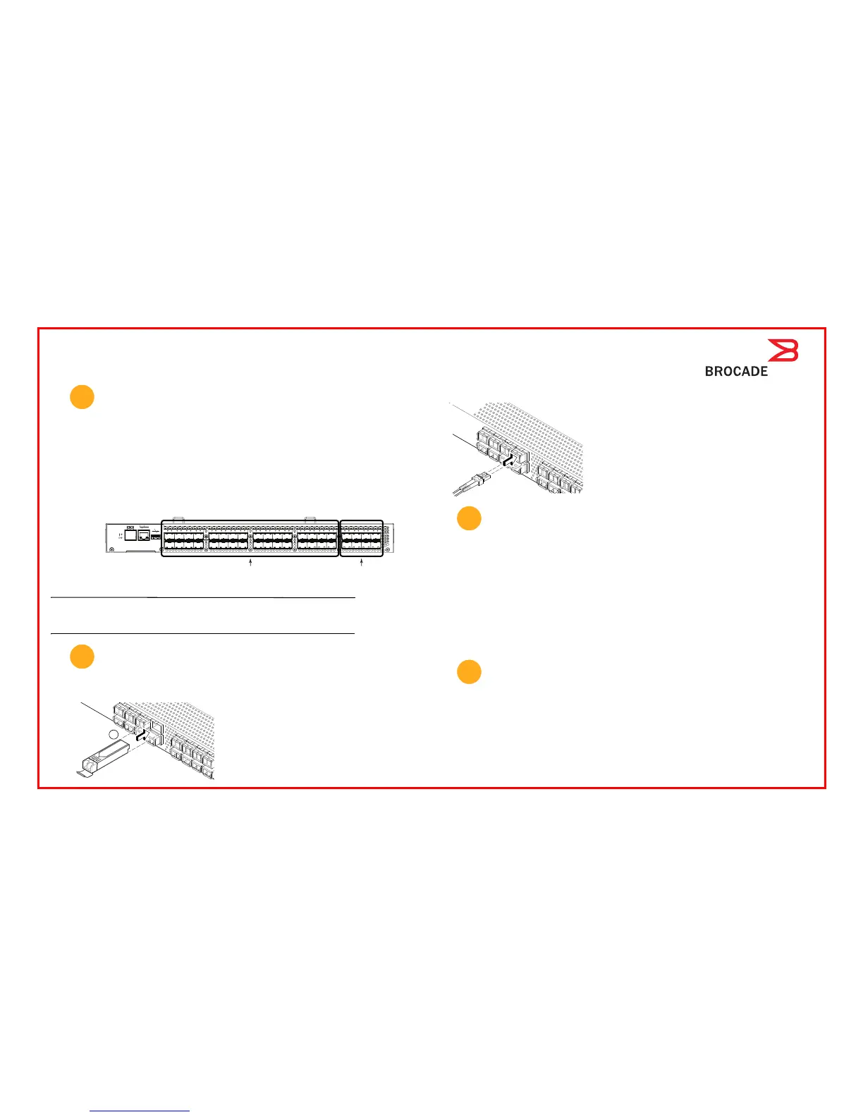
5. Enter ag - -mapshow to display the F_port to N_port mapping. The F_ports connect to servers, and the N_ports connect to
Fabrics. The following figure summarizes default port assignments and mapping options for Access Gateway on the
Brocade 5100.
ATTENTION
The Automatic Port Configuration Policy (APC) is disabled in the factory default. The switch should be in a disabled state before
activating or deactivating the APC policy. When the APC policy is enabled, all the existing F_Port to N_Port mappings are deleted.
When the APC policy disabled, N_Port configuration and F_Port to N_Port mapping will revert back to the factory default.
Connect Devices
1. Install the SFP transceivers in the Fibre Channel ports on the switch.
2. Connect Fibre Channel cables. Using a mapping scheme appropriate for your installation, connect servers to ports in the
F_port group, and edge switches to ports in the N-port group (see the figure in step six).
.
Bring up the Management Interface
1. From your management console, log in to the switch. If Web Tools is available on the computer, you may launch an internet
browser window and type in the IP address as the http:// address. If Web Tools is not available, or if you prefer to work from
a command line interface, launch a Telnet window, and log in to the switch IP address through Telnet. In either case, use
the default admin user name and password, unless you have already changed them.
2. If you successfully log in, quit the terminal application program on the setup computer, and physically disconnect the setup
computer from the serial port and Ethernet port.
If you are unsuccessful, you may want to use the setup computer to troubleshoot the connection. Typically, the problem is
incorrect IP addressing. You may want to issue a ping command from the setup computer to the management console to
test the IP path.
3. If you logged in with the default password, change it now. As a precaution, you may want to write down the password and
store it in a secure location for future reference.
Configure and Administer Access Gateway
You are now ready to configure and administer Access Gateway. Refer to the Access Gateway Administrator’s Guide for detailed
information about Access Gateway concepts, configuration procedures, and administrative operations.
6
0 1 2 3 8 9 10 11
16
17
18 19
24 25 26 27
32 33 34 35
4 5 6 7 12 13 14 15 20
21
22 23
28 29 30 31
36
37 38 39
Ports 0-31 are F_ports
Ports 32-39 are N_ports
with failover and
failback enabled.
Default mapping:
0-3 to 32 8-11 to 34 16-19 to 36 24-27 to 28
4-7 to 33 12-15 to 35 20-23 to 37 28-31 to 39
7
4- 01
!
1a
a. Remove any protector plugs from the SFP
transceivers you are going to use, and position and
insert each SFP transceivers as required (right side
up in the top row of ports and upside down in the
bottom row of ports) until it is firmly seated.
b. Close the latching bale.
!
a. Remove plastic protector caps from the Fibre Channel
cable ends (if there are any), and position the cable
connector so that it is oriented correctly.
b. Insert the cable connector into the SFP until it is firmly
seated and the latching mechanism clicks.
8
9
 Loading...