Do you have a question about the Brocade Communications Systems DCX 8510-4 and is the answer not in the manual?
Explains the structure and organization of the manual.
Details the supported hardware and software versions.
Lists new information or changes in the document.
Explains text formatting, command syntax, and notices.
Provides information on trademarks and their owners.
Lists additional Brocade and industry-specific documentation.
Guides users on how to contact support for assistance.
Provides contact information for submitting feedback on the document.
Describes the key features of the Brocade DCX 8510-4.
Details the hardware components of the Brocade DCX 8510-4.
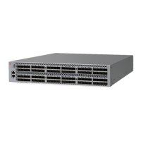
Illustrates and describes the port side of the chassis.
Illustrates and describes the nonport side of the chassis.
Lists and describes the available blades for the Brocade DCX 8510-4.
Explains the high-availability design features of the system.
Details the error detection and correction mechanisms for data reliability.
Describes features that enhance and ensure system serviceability.
Lists the features of the Brocade Fabric OS.
Highlights the key security features available for the system.
Explains how the system is managed over the network.
Lists the time and items needed for installation tasks.
Details prerequisites and preparations for installing the chassis.
Provides step-by-step instructions for unpacking and installing the unit.
Lists the contents of the Brocade DCX 8510-4 package.
Explains how to connect and provide power to the chassis.
Describes the port numbering scheme for various blades.
Details the numbering and usage of chassis slots for blades.
Provides guidelines and recommendations for managing cables.
Provides instructions for installing QSFP cables.
Outlines the initial configuration parameters required for the chassis.
Details how to establish a serial connection to the console port.
Provides steps for logging into the system via the serial console.
Explains how to configure IP addresses for the chassis and blades.
Describes how to properly log out and disconnect the serial console.
Details how to establish an Ethernet connection for configuration.
Explains how to customize the switch name.
Explains how to customize the chassis name.
Describes how to set a unique domain ID for each switch in the fabric.
Explains how to set the system date and time for logging.
Explains how to verify the WWN Based persistent port identifier setting.
Guides users on how to check enabled software licenses.
Covers the installation of transceivers and cables for SFPs and QSFPs.
Provides recommendations for organizing and managing cables.
Explains how to verify system operation and back up the configuration.
Provides steps to safely power off the chassis.
Provides information for determining component status using LEDs and CLI commands.
Explains how to check the status of port or application blades using LEDs.
Details how to check the status of a control processor blade using LEDs.
Explains how to check the status of a core switch blade using LEDs.
Provides steps to determine the status of a power supply using LEDs.
Explains how to check the status of a blower assembly using LEDs.
Details how to check the status of a WWN card using LEDs and messages.
Introduces the procedures for removing and replacing field-replaceable units (FRUs).
Provides essential electrostatic discharge precautions for handling FRUs.
Details the procedure for removing and replacing the chassis door.
Explains how to remove and replace cable management finger assemblies.
Details the procedure for removing and replacing blower assemblies.
Covers the removal and replacement of port, application, and encryption blades.
Details the procedure for removing and replacing blade filler panels.
Guides users through the process of removing and replacing CP8 blades.
Guides users through the process of removing and replacing the entire chassis.
Details critical information to record before chassis replacement.
Explains how to remove and replace CR16-4 core switch blades.
Provides steps for removing and replacing power supply units.
Covers the removal and replacement of WWN cards.
Provides instructions for removing and replacing optical transceivers.
Explains how to remove and replace QSFP cables for inter-chassis links.
Describes the specifications for Fibre Channel ports.
Details the basic power specifications for the power supply units.
Lists the types of power cords provided and their country-specific plugs.
Provides data transmission ranges for transceivers, speeds, and cables.
Lists third-party cables qualified for the FC8-64 high density port blade.
Alerts users to dangers, cautions, and attention notices in the manual.
Describes the regulatory compliance requirements for the system.
Lists the general specifications for the Brocade DCX 8510-4.
Details China RoHS environmental regulatory compliance requirements.
Details the system architecture of the Brocade DCX 8510-4.
Provides information on the system's physical dimensions and weight.
Lists the weights of compatible blades and field-replaceable units.
Outlines the facility requirements for correct operation of the chassis.
Lists the environmental operating ranges for the Brocade DCX 8510-4.
Introduces application and encryption blades available for the system.
Describes the features and capabilities of the FS8-18 encryption blade.
Details the features and functionality of the FX8-24 extension blade.
Introduces diagnostic aids and troubleshooting steps for the fabric.
Explains how to obtain chassis and component status using CLI commands.
Guides users on interpreting Power-On Self-Test and boot results.
Describes automatic and manual diagnostic tests for hardware and firmware.
Provides a list of issues, causes, and recommended actions for troubleshooting.
Shows mappings from numbered ports to slotShow port numbers for the CR16-4 blade.
Illustrates the port layout and LEDs for the FC8-64 port blade.
Illustrates the port layout and LEDs for the FC8-32E port blade.
Illustrates the port layout and LEDs for the FC8-48E port blade.
Illustrates the port layout and LEDs for the FC16-32 port blade.
Illustrates the port layout and LEDs for the FC16-48 port blade.
Illustrates the port layout and LEDs for the FS8-18 encryption blade.
Illustrates the port layout and LEDs for the FX8-24 extension blade.
| Model | DCX 8510-4 |
|---|---|
| Category | Switch |
| Product Type | Fibre Channel Switch |
| Product Series | DCX Series |
| Fibre Channel Speed | 16 Gbps |
| Fibre Channel Standard | FC-PI-4, FC-PI-5 |
| Power Supply | Dual redundant power supplies |
| Cooling | Redundant, hot-swappable fans |
| Management | Web-based, CLI, SNMP |
| Hot-Swappable Components | Power supplies, fans, blades |
| Redundancy | Power supplies, fan modules |
| Supported Protocols | Fibre Channel |
| Form Factor | Chassis-based |