4 Brocade DCX 8510-4 Backbone Hardware Reference Manual
53-1002177-06
Brocade DCX 8510-4 hardware components
1
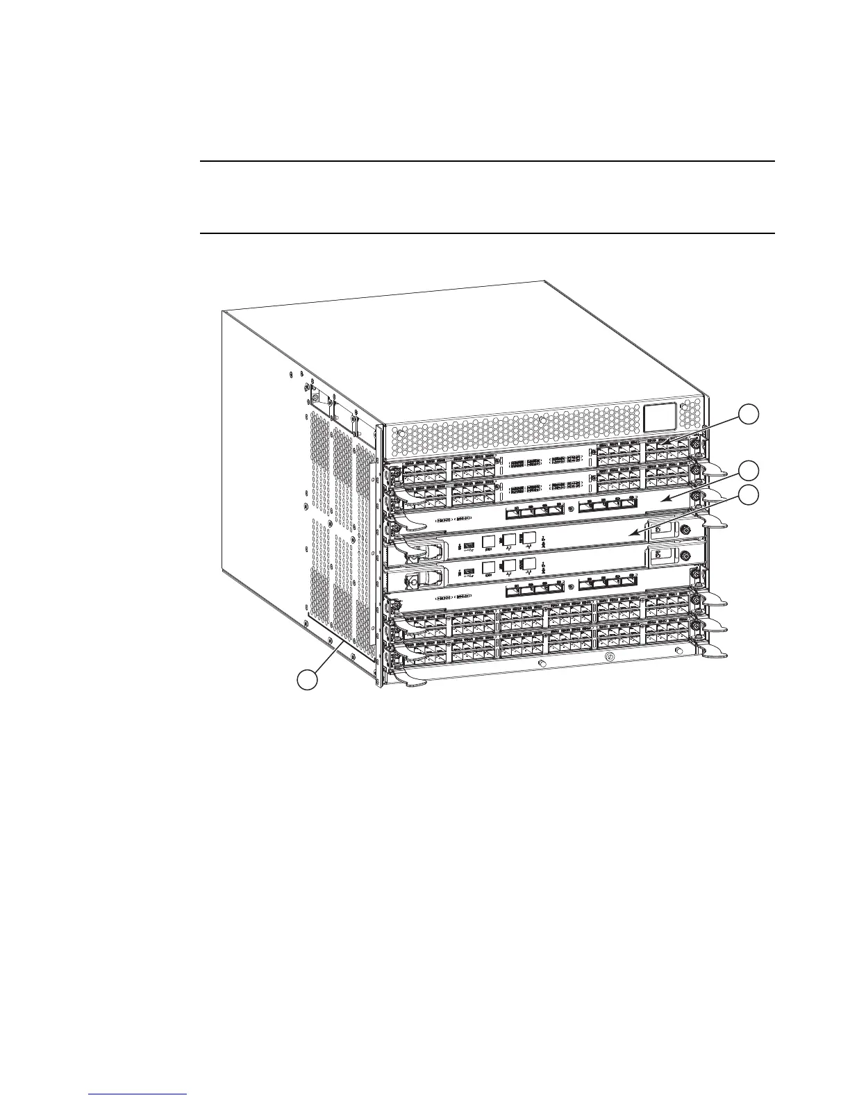
Port side of the Brocade DCX 8510-4
Airflow in the Brocade DCX 8510-4 is from the nonport side to the left side and port side of the
chassis (viewed from the port side) and out the exhaust vents. If you use the Port Side Exhaust Kit,
the air vents are all on the port side of the chassis (see Figure 2).
Figure 1 displays a sample configuration of the port side of the Brocade DCX 8510-4.
FIGURE 1 Port side of the Brocade DCX 8510-4 (sample configuration)
1 Port blade (FC16-32) 3 Control processor blade (CP8)
2 Core switch blade (CR16-4) 4 Exhaust vent

 Loading...