Brocade DCX 8510-4 Backbone Hardware Reference Manual 65
53-1002177-06
Control processor blade (CP8) removal and replacement
5
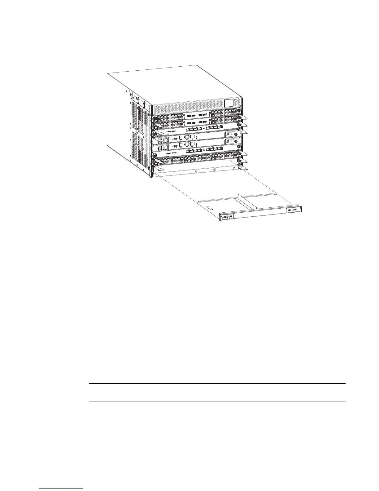
FIGURE 21 Removal and replacement of the blade filler panel
Replacing a filler panel
Do not leave a slot empty. This will adversely affect cooling of the chassis.
1. Orient the filler panel.
2. Slide the filler panel into the slot until it is firmly seated.
3. Tighten the thumbscrews.
4. Replace the chassis door.
Control processor blade (CP8) removal and replacement
This document describes how to remove and replace a control processor (CP8) blade. Each chassis
has two CP8 blades. In the DCX 8510-4 they are located in slots 4 and 5.
The CP8 blade is compatible only with the Brocade DCX Backbones (including the 8510s).

 Loading...