Brocade DCX 8510-4 Backbone Hardware Reference Manual 19
53-1002177-06
Chassis slots
2
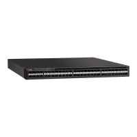
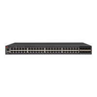
• FC16-48 port blade — Ports are numbered from 0 through 23 from right to left on the lower set
of ports and 24 through 47 from right to left on the upper set of ports.
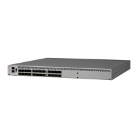
• CR16-4 core blade — Inter-chassis link connectors are numbered from 0 through 7 from right
to left. Each connector is actually a group of four 16 Gbps ports.
• FS8-18 blade — The 16 physical Fibre Channel ports on this blade are numbered 0 through 15
from right to left. The two 10/100/1000 BaseT ports are numbered from the bottom as GE0
and GE1.
• FX8-24 blade — Ports are numbered in groups. The FC ports are numbered from 0 through 11
in two horizontal rows of six ports starting from the lower right and upper right in the right-hand
group of 12 ports. They are labeled FC on the front panel diagram. The two 10GbE ports are 0
and 1 and are in the lower row just to the left of the FC ports. They are labeled 10GE on the
front panel diagram. The GbE ports are numbered 0 through 9 and are in both rows to the left
of the FC and 10GE ports. They are labeled GE on the front panel diagram. Up to three FC
trunking groups are permitted. The three groups are defined as follows:
- Trunk group 0: FC ports 0, 1
- Trunk group 1: FC ports 6, 7
- Trunk group 2: FC ports 2, 3, 4, 5, 8, 9, 10, 11
For more information on the FC8-64 port blade see Figure 38 on page 136. For more information
on the front panel diagrams on the FX8-24 application blade see Figure 44 on page 138.
Chassis slots
Chassis slots are numbered 1 through 8, from bottom to top when facing the port side of the
Brocade DCX 8510-4. Control processor blades (CP8) can be installed only in slots 4 and 5. Core
switch blades (CR16-4) can be installed only in slots 3 and 6. The rest of the slots, 1, 2, 7, and 8,
can be filled with port, application, or encryption blades. Unused slots must be filled with blade
filler panels to maintain adequate cooling.
Cable management
The cable management finger assemblies (Figure 19) are attached to the chassis to either side of
the port side of the chassis and allow for simple cable management. The cable management finger
assemblies can be installed without service disruption.
Route the cables across in front of the blades to keep LEDs visible. Leave at least one meter of
slack for each fiber-optic cable to provide room to remove and replace blades.
The minimum radius to which a 50 micron cable can be bent under full tensile load is 5.1 cm (2 in.).
For a cable under no tensile load, that minimum is 3.0 cm (1.2 in.).
Cables can be organized and managed in a variety of ways, for example, using cable channels on
the sides of the cabinet or patch panels to minimize cable management. Following is a list of
recommendations:

 Loading...