6
TABLE 2
Total input rating of all
connected appliances
Flue inside diameter (in) Minimum base temperature (ºF)
for chimney height (ft) of :
kW kBtu/h USGPH Min. Max. 11 20 28 36
21 70 0.50 3 5 300 400 535 725
27 91 0.65 3 5 275 340 430 535
31 105 0.75 4 5 260 320 380 475
36 119 0.85 4 5 250 300 355 430
41 140 1.00 4 6 225 300 365 430
51 175 1.25 4 6 240 275 320 365
1.5) AIR FOR COMBUSTION
WARNING
Poisonous carbon monoxide gas hazard.
Comply with ANSI/NFPA (U.S.) or CSA (Canada)
standards for the installation of Oil Burning
Equipment and applicable provisions of local
building codes to provide combustion and
ventilation air.
Failure to provide adequate combustion and
ventilation air can result in personal injury and/or
death.
1.5.1) General
Oil furnaces must have an adequate supply of combustion air. It is
common practice to assume that older homes have sufficient
infiltration to accommodate the combustion air requirement for the
furnace. However, home improvements such as new windows, doors,
and weather stripping have dramatically reduced the volume of air
leakage into a home.
Home air exhausters are common. Bathroom and kitchen fans, power
vented clothes dryers, and water heaters all tend to create negativ e
pressure in the home. Should this occur, the chimney becomes less
and less effective and can easily downdraft.
Heat recovery ventilation (HRV) systems are gaining in popularity.
HRVs are not designed to supply combustion air. If not properly
balanced, a serious negative pressure condition could develop in the
dwelling.
1.5.2) Contaminated Combustion Air
Installation in certain areas or types of structures will increase the
exposure to chemicals or halogens which may harm the furnace.
These cases will require that only outside air be used for combustion.
The following areas or types of structures may contain or have
exposure to the substances listed below. The installation must be
evaluated carefully as it may be necessary to provide outside air for
combustion.
a. Commercial buildings;
b. Buildings with indoor pools;
c. Furnaces installed near chemical storage areas.
Exposure to these substances:
a. Permanent wave solutions for hair;
b. Chlorinated waxes and cleaners;
c. Chlorine based swimming pool chemicals;
d. Water softening chemicals;
e. De-icing salts or chemicals;
f. Carbon tetrachloride ;
g. Halogen type refrigerants ;
h. Cleaning solvents (such as perchloroethylene);
i. Printing inks, paint removers, varnishes, etc..;
j. Hydrochloric acid;
k. Solvent cements and glues;
l. Antistatic fabric softeners for clothes dryers;
m. Acid based masonry cleaning materials.
1.6) OIL TANKS AND LINES
Check your local codes for the installation of the tank and accessories.
A manual shut-off valve and an oil filter shall follow in sequence from
tank to burner. Be sure that the oil line is clean before connecting to
the burner. The oil line should be protected to eliminate any possible
damage. Installations having the fuel oil tank below the burner level
must employ a two pipe fuel supply system with an appropriate fuel
pump (more than an 8 foot rise uses a 2 stage pump and more than a
16 foot rise an auxiliary pump).
At the beginning of each heating season or each year, check the
complete oil distribution system for leaks.
Follow the pump instructions to determine the size of tubing you need
in relation to the rise, or the horizontal distance.
1.7) BURNER INSTALLATION
Mount burner on the 3 bolts fixed to the mounting plate. Use the
gasket supplied between burner mounting support and burner. Install
washer and nuts. The air tube must be centred in the opening of the
combustion chamber.
CAUTION
Do not turn on the burner until you have checked the
polarity
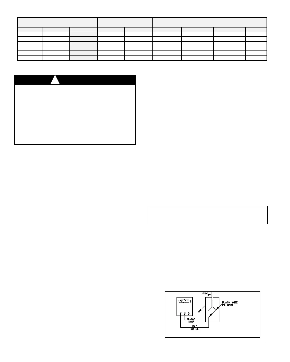
Checking the polarity
Oil burners used on furnaces have solid state control systems which
make them sensitive to the proper connections of the hot and neutral
power lines. The controls will be damaged if the two lines are
reversed. Refer to Figure 1.
1. Set your voltmeter to line voltage;
2. Place one prong on your grounded electric entry box and one
prong on the black wire;
3. Read the voltage;
4. If the voltage is zero, check the white wire. If line voltage shows,
reverse the 115-volt leads entering the furnace junction box.
FIGURE 1
DNS-0864 Rev. A
 Loading...