Page 17/26IOM Single Case BiRotor Plus R06
3. Remove O-ring.
4. Holding the measuring unit assembly by the ribs,
carefully lift straight up until the assembly clears
the inlet housing.
5. Place the measuring unit in the horizontal
position.
At this stage the assembly can be inspected for wear
or damage. If the assembly had jammed it may be
possible to unblock the rotors by fl ushing it with a
cleaning solvent or kerosene without the need for
further disassembly.
Further disassembly of the measuring unit for clean-
ing or inspection can be achieved while maintaining
clearance settings. This procedure is covered in the
next section.
10.6 Measuring Unit Disassembly While
Maintaining Clearance Settings
1. Place a folded rag between the timing gears to
prevent the rotors from turning during
disassembly.
2. Remove the pulse wheel by removing the screw ,
washer, and retaining washer.
3. Remove the screw from the end plate at the
timing gear end of the measuring unit assembly.
NOTE:
A fl at head screwdriver may be used in conjunction
with the slots on the end plate to aid in its removal.
Excessive force is not required.
4. Use a plastic or rubber mallet and strike the rotor
shafts at the pulse wheel end of the housing to aid
in the removal of the rotor assembly.
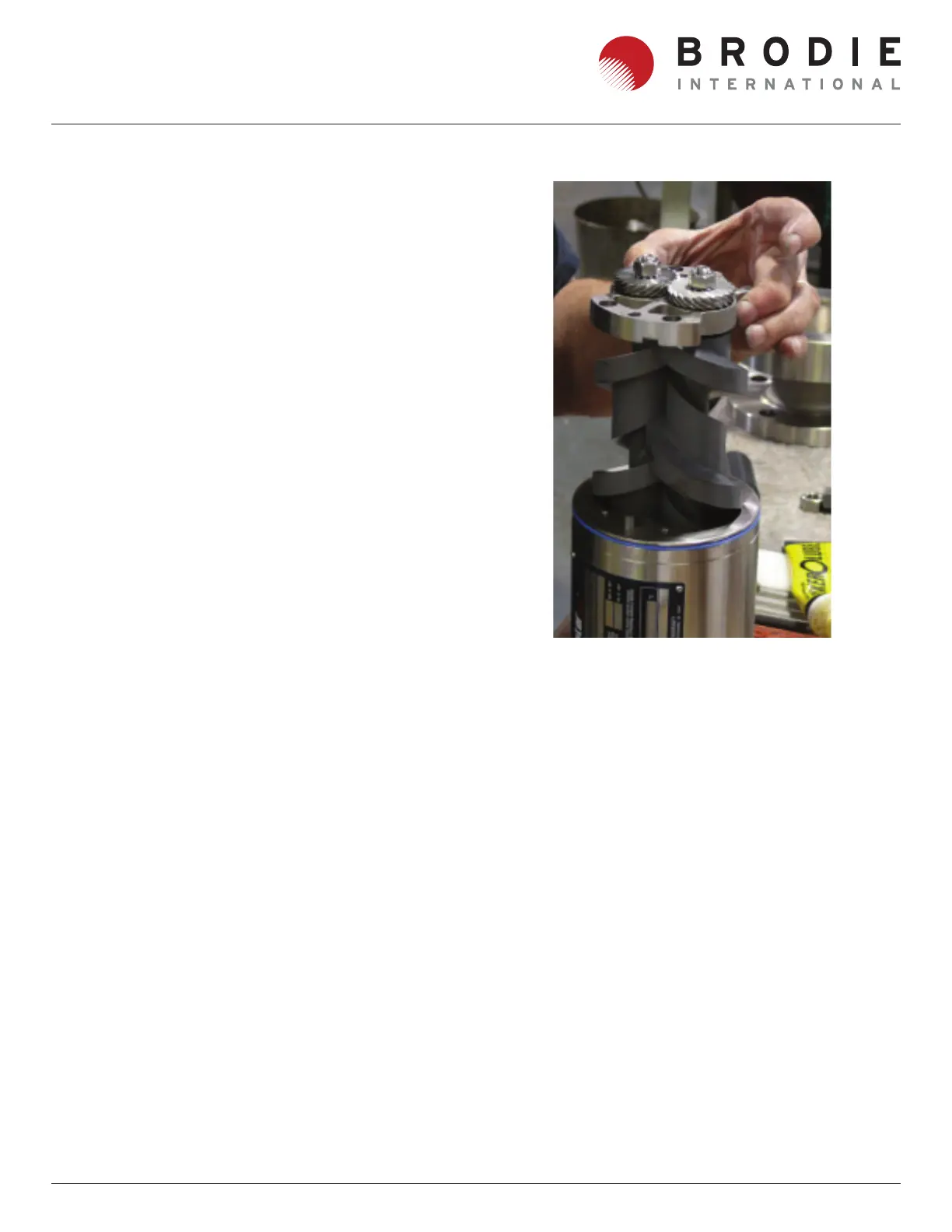
Figure 10-3 Measuring Unit DIsassembly
5. Once the rotor assembly has been removed from
the housing any blockage or foreign material can
be cleaned away.
At this stage the meter can be reassembled by
reversing the disassembly procedures without the
need to reset any clearances.
10.7 Complete Disassembly
Continuing from step 3 above.
1. Restrict the rotor movement by placing a folded
rag between the timing gears.
2. Undo nuts , then remove them from the rotor
shafts. The timing gears can be released from the
shaft by striking them on the fl at surface with a
plastic or rubber mallet.
3. Remove the rotors from the end plate by gently
tapping the rotor shafts with a plastic or rubber
mallet. Remove the o-rings from the rotor shafts.