Page 18/26IOM Single Case BiRotor Plus R06
4. The bearings can be removed from the end plates
by pressing on the inner race of the bearings from
the outside of the plate. If the bearings are
removed from the endplates, they must be
replaced.
5. Remove the other end plate from the measuring
element housing and remove bearings.
10.8 Complete Disassembly of the Measuring Unit
1. Ensure all parts are clean and free of debris.
2. Lubricate all bearings with a light oil, Note all
o-rings should be replace with new ones during
reassembly, all o-rings should be lubricated with a
compatible lubrication compound.
3. Press bearings in to the end plates, use a hand
press and ensure that the bearing is pressed on
the outer race to avoid damage. The bearing races
should be fl ush with the bottom of the end plate
once the bearings have been pressed in correctly.
The outer race of an old bearing can be used to
assist in proper seating.
4. Attach one end plate to the measuring unit body
outlet (the outlet end is the right hand side of the
measuring unit housing when the nameplate lable
is facing towards you). Align the dowel pin and
gently tap into place with a plastic mallet. Once
fully seated secure the end plate with screws.
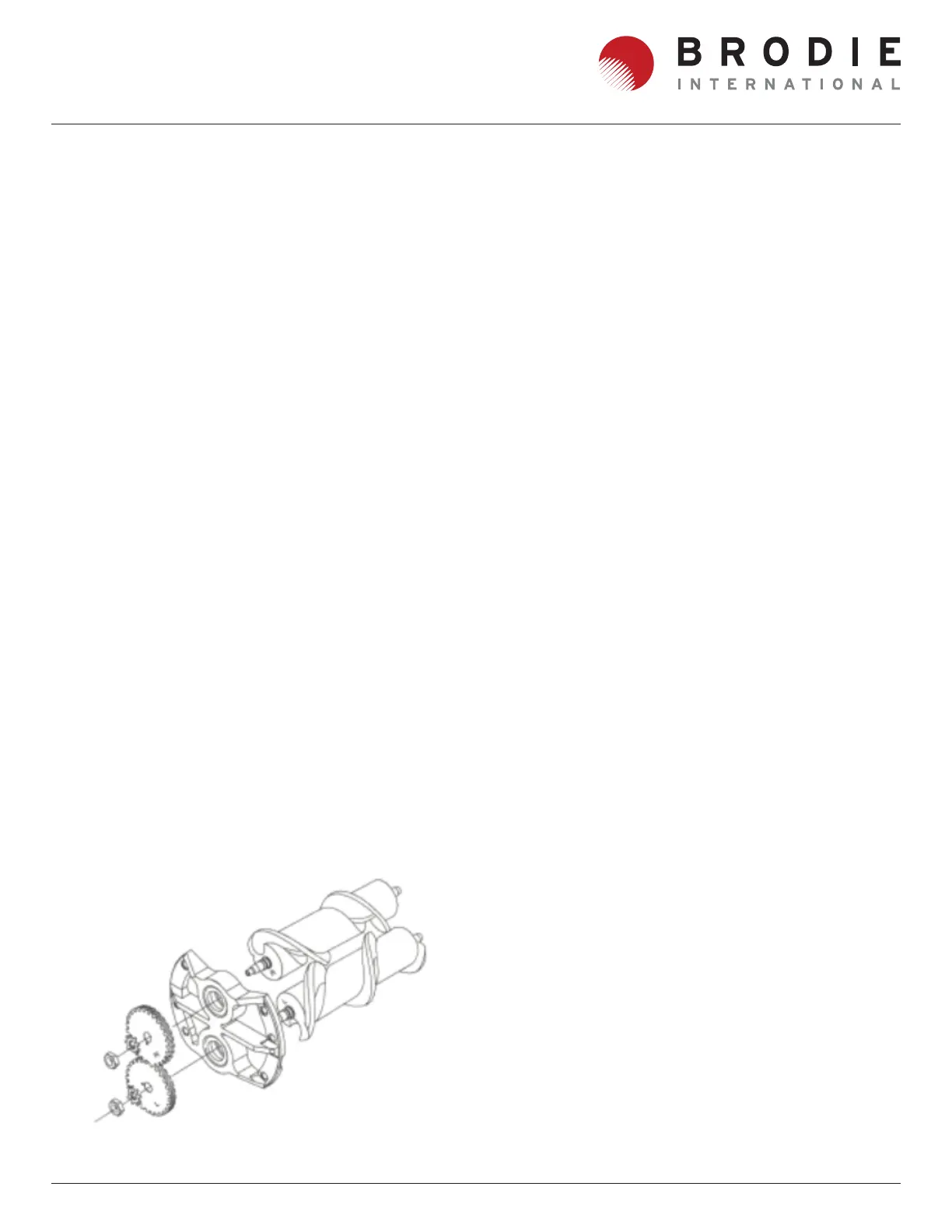
Each rotor and timing gear is marked with a R or an L,
During assembly the inscriptions need to be matched.
(To orientate the rotors during assembly lay the
measuring unit housing on it’s side so that the name
plate label in on the bottom and the outlet end facing
away from you. Then with the tapered ands of the
rotors also facing away from you, the right hand rotor
goes in the right hand cavity and the left hand rotor
goes in the left hand cavity)
5. Lubricate O-rings and install on the rotor shafts.
Mesh the two rotors together ensuring that the
tapered shafts are at the same ends. The rotors
should be held together with the tapered end of
the shaft facing the end plate which is attached
to the measuring element housing. While keeping
the rotors meshed and even, insert them into the
measuring chamber, use a plastic or rubber mallet
to gently seat the rotor shafts into the bearings.
6. Install the other end plate and screws on to the
other end of measuring element body, ensure that
the rotor shafts seat within the bearings.
7. Place the timing gears onto the respective
tapered rotor shaft.
8. Install the lock nuts on to the rotor shafts, tighten
these only fi nger tight until the clearances have
been correctly set. Refer to the setting clearance
section.
9. Replace the pulse wheel on the right hand rotor,
Use thread locking compound on the threads and
secure with the retaining washer, washer and
screw.
10. Install the o-rings (12) onto the main housing.
11. Lower the complete measuring unit assembly
into the inlet housing (21), align the dowel pin and
ensure it is fully located.
12. Insert studs into the four holes in the measuring
unit housing loosely attached four nuts to the
studs at the inlet side.
Figure 10-4 Rotor/gear Orentation